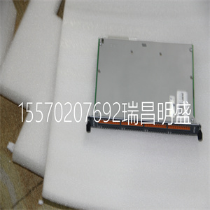
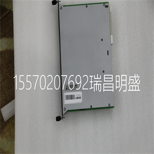
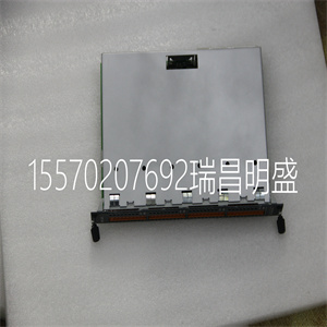
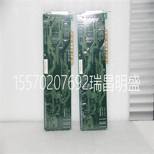
DO321B ■ PCI card in 1- through 4-axis versions: DMC-18x2 where x=1,2,3,4 axes ■ User-configurable for stepper or servo motors on any combination of axes. Optional firmware for piezo-ceramic motors. Configurable for sinusoidal commutation ■ Accepts up to 12 MHz encoder frequencies for servos. Outputs up to 3 MHz for stepper motors ■ PID compensation with velocity and acceleration feedforward, integration limits, notch filter and low-pass filter ■ Modes of motion include jogging, point-to-point positioning, contouring, linear and circular interpolation, electronic gearing and ECAM. Features elliptical scaling, slow-down around corners, infinite segment feed, and feedrate override ■ Over 200 English-likecommands including conditional statements and event triggers ■ Non-volatile memory for programs, variables, and arrays. Multitasking for concurrent execution of up to eight programs ■ Home input and forward and reverse limits accepted for every axis ■ 8uncommitted inputs and 8 outputs ■ High speed position latch for each axis and output compare ■ Expansion for 64 I/O with optional DB-14064 board ■ 100-pin SCSI connector. ICM-2900 breaks-out 100-pin cable intoscrew terminals ■ AMP-19540 connects toPCI controller with 100-pin cable and provides four amplifiers for 500 W servos ■ Communication drivers for Windows, Mac OSX, and Linux ■ CE certified ■ Custom hardware and firmware options available Product Description The DMC-18x2 Series are PCI bus motion controllers for single and multi-axis applications.The Econo Series is designed for the most cost-sensitive applications. To minimize cost, the following features are not available on the DMC-18x2: five through eight axes of control, optical isolation on inputs, uncommitted analog inputs, dual encoder inputs, and the auxiliary FIFO and DPRAM communication channel. The DMC-18x2 incorporates a 32-bit microcomputer and provides advanced features such as PID compensation with velocity and acceleration feedforward, memory with multitasking for simultaneously running up to eight programs, and uncommitted I/O for synchronizing motion with external events. Modes of motion include point-to-point positioning, jogging, linear and circular interpolation, contouring, electronic gearing, and electronic cam. Likeall Galil controllers, the DMC-18x2 motor controllers use a simple, intuitive command language which makes them very easy to program. GalilTools softwarefurther simplifies system set-up with “onebutton” servo tuning and real-time display of position and velocity information. DO321B 4-axis PCI controller www.galilmc.com / Galil Motion Control, Inc. 1ECONO PCI Bus Econo Series, 1– 4 axes DMC-18x2 Series www.servo2go.com sales@servo2go.com www.servo2go.com Toll Free Phone: 877-378-0240 Toll Free Fax: 877-378-0249 sales@servo2go.com www.servo2go.com Sold & Serviced By: 2 www.galilmc.com / Galil Motion Control, Inc. ECONO * DMC-18x2 revision E and higher require 3.3V from PCI bus. Order DMC-18x2-3VREG tohave aregulator installed to allow 5V only supply. DMC-18x2 Series PCI Bus Econo Series, 1–4 axes Specifications System Processor ■ Motorola 32-bit microcomputer Communications Interface ■ DMC-18x2: PCI with bi-directional FIFO ■ 32-bit PCI interface. 64-bit compatible. 5 V/3.3 V Commands are sent in ASCII. A binary communication mode is also available as a standard feature Modes of Motion: ■ Point-to-point positioning ■ Position Tracking ■ Jogging ■ 2D Linear and Circular Interpolation with feedrate override ■ Linear Interpolation for up to 4 axes ■ Tangential Following ■ Helical ■ Electronic Gearing with multiple masters and ramp-to-gearing ■ Gantry Mode ■ Electronic Cam ■ Contouring ■ Teach and playback Memory ■ Program memory size—1000 lines × 80 characters ■ 254 variables ■ 8000 array elements in up to 30 arrays Filter ■ PID (proportional-integral-derivative) with velocity and acceleration feedforward ■ Notch filter and low-pass filter ■ Velocity smoothing to minimize jerk ■ Integration limits ■ Torque limits ■ Offset adjustments ■ Option for piezo-ceramic motors Kinematic Ranges ■ Position: 32 bit (±2.15 billion counts per move; automatic rollover; no limit in jog or vector modes) ■ Velocity: Up to 12 million counts/sec for servo motors ■ Acceleration: Up to 67 million counts/sec2 Uncommitted Digital I/O DIGITAL INPUTS DIGITAL OUTPUTS ANALOG INPUTS DMC-18x2 8 8 0 High Speed Position Latch ■ Uncommitted inputs 1-4 latch X,Y, Z,W (latches within 0.1 microseconds) Dedicated Inputs (per axis) ■ Main encoder inputs—Channel A, A-, B,B-,I, I- (±12 V or TTL) ■ Forward and reverse limit inputs ■ Home input ■ Selectable high-speed position latch input ■ Selectable abort input for each axis Dedicated Outputs (per axis) ■ Analog motor command output with 16-bit DAC resolution ■ Pulse and direction output for step motors ■ PWM output also available for servo amplifiers ■ Amplifier enable output ■ Error output (per card) ■ High-speed position compare output (per card) Minimum Servo Loop Update Time STANDARD -FAST† ■ 1–2 axes: 250 µsec 125 µsec ■ 3–4 axes: 375 µsec 250 µsec Maximum Encoder Feedback Rate ■ 12 MHz Maximum Stepper Rate ■ 3 MHz (Full, half or microstep) Power Requirements ■ DMC-18x2: +5V 750 mA -12V 20 mA +12V 20 mA +3.3V 100 mA* Environmental ■ Operating temperature: 0–70º C ■ Humidity:20–95% RH, non-condensing Mechanical ■ DMC-18x2: 7.275" × 4.2" Connectors ■ 100-pin HD SCSI †Reduced feature set for -FAST. www.servo2go.com sales@servo2go.com www.servo2go.com Toll Free Phone: 877-378-0240 Toll Free Fax: 877-378-0249 sales@servo2go.com www.servo2go.com Sold & Serviced By: DMC-18x2 Series PCI Bus Econo Series, 1–4 axes ECONO Instruction Set Servo Motor FA Acceleration feedforward FV Velocity feedforward IL Integrator limit KD Derivative constant KI Integrator constant KP Proportional constant NB Notch bandwidth NF Notch frequency NZ Notch zero OF Offset PL Pole SH Servo here TL Torque limit TM Sample time TK Peak torque Stepper Motor KS Stepper motor smoothing LC Low current QS Error magnitude YA Step drive resolution YB Step motor resolution YC Encoder resolution YR Error correction YS Stepper position maintenance Internal Sine Commutation BA Brushless axis BB Brushless phase BC Brushless calibration BD Brushless degrees BI Brushless inputs BM Brushless modulo BO Brushless offset BS Brushless setup BZ Brushless zero I/O AL Arm latch CB Clear bit CO Configure I/O points II Input interrupt OB Define output bit OC Output compare function OP Output port SB Set bit @IN[x] Stateof digital input x @OUT[x] State of digital output x BN Burn parameters BP Burn program BV Burn variables and arrays CE Configure encoder type CN Configure switches CW Data adjustment bit DE Define dual encoder position System Configuration DP Define position EI Enable interrupts EO Echo IT Independent smoothing LZ Leading zeros format MO Motor off MT Motor type PF Position format QD Download array RS Reset ˆRˆS Master reset VF Variable format Math Functions @ABS[x] Absolute value of x @ACOS[x] Arc cosine of x @ASIN[x] Arc sine of x @ATAN[x] Arc tangent of x @COM[x] 1’s complement of x @COS[x] Cosine of x @FRAC[x] Fraction portion of x @INT[x] Integer portion of x @RND[x] Round of x @SIN[x] Sine of x @SQR[x] Squareroot of x @TAN[x] Tangent Interrogation LA List arrays LL List labels LS List program LV List variables MG Message command QR Data record QU Upload array QZ Return data record RL Report latch RP Report command position ˆRˆV Firmware revision information SC Stop code TB Tell status TC Tell error code TD Tell dual encoder TE Tell error TI Tell input TP Tell position TR Trace program TS Tell switches TT Tell torque TV Tell velocity TZ Tell I/O configuration Programming BK Breakpoint DA Deallocate variables/arrays DL Download program DM Dimension arrays ED Edit program ELSE Conditional statement ENDIF End of cond. statement EN End program HX Halt execution IF If statement IN Input variable JP Jump JS Jump to subroutine NO No-operation—for comments RA Record array RC Record interval RD Record data RE Return from error rout |