
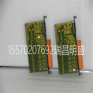
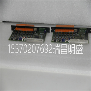


EMG22-RELKSR-23021
2) 如果使用IRQ编号,则为IRQ编号
提供设置信息后,终端显示器应显示冒号:。如果不显示,则
收到冒号,计算机无法识别您的18x2控制器。
我们的DOS实用程序接受命令行参数。为了将这些实用程序与1802控制器一起使用,
包括参数-c1802。有关命令行参数的完整列表,请键入实用程序名称
用“?”作为参数(例如SEND2DMC?)。
如果需要帮助,请咨询工厂。
步骤6.确定用于正弦换向的轴
*仅当控制器用于控制无刷电机时,才需要此步骤
正弦换向。
命令BA用于选择正弦换向的轴。例如,BAXY设置X
Y为正弦换向轴。对于DMC-18X2,多可以设置两个轴
正弦换向,需要DMC-1842。
Artisan技术集团-质量仪器…保证|(888)88-SOURCE| www.artistg.com
12● 2章DMC-18x2的入门
关于配置正弦换向的注意事项:
命令BA重新配置控制器,使其少了一个“标准”控制轴
每个轴都使用正弦换向。例如如果命令BAX被给予DMC-1842
控制器,控制器将重新配置为DMC-1832,并在以下情况下显示:
审问。在这种情况下,高轴用于正弦换向的二阶段
无法连接以控制单独的电机。请注意,控制器上的高轴永远不能
可配置为正弦换向。
与所选轴相关联的DAC表示一相位。二阶段使用
高可用DAC。当两个轴配置为正弦换向时,控制器将:
分别为X轴换向的一阶段和二阶段分配X轴和Z轴DAC
以及分别用于Y轴换向的一阶段和二阶段的Y轴和W轴DAC。
高正弦换向轴将分配给高可用DAC和低可用DAC
正弦换向轴将分配给低可用DAC。
步骤7.连接放大器和编码器。
一旦在软件和DMC-18x2之间建立了通信,您就可以开始了
连接运动控制系统的其余部分。运动控制系统通常包括:
互连模块(ICM-1900或ICM-2900)、用于每个运动轴的放大器和用于驱动的电机
将来自放大器的电流转换为运动扭矩。Galil还提供AMP-19X0
其为ICM-1900,配备有用于刷式直流电机的X数伺服放大器。
如果您使用的是ICM/AMP-1900或ICM-2900,请将100针电缆连接到DMC-18x2和
连接器位于互连板上。互连提供用于访问的螺钉端子
连接到100引脚连接。
系统连接程序将取决于系统部件和电机类型。任何组合
DMC-18x2可使用多种电机类型。如果要使用正弦换向,请使用特殊电机
必须注意轴的重新配置。
以下是连接运动控制系统的一步:
步骤A.将电机连接到放大器,而不连接到控制器。咨询
放大器文档以获取正确的说明。连接并打开放大器
电源。如果放大器工作正常,电机应保持平稳
当放大器通电时。
步骤B.连接放大器启用信号。
在进行从放大器到控制器的任何连接之前,您需要验证:
放大器的地电平要么浮动,要么与地电位相同。
警告:当放大器接地未与电源线隔离或其电位不同时
与计算机接地相比,可能会对计算机、控制器和放大器造成严重损坏。
如果您不确定地电位,请连接两个接地端子
通过10 KΩ电阻器发送信号(放大器接地和接地),并测量两端的电压
电阻器。只有当电压为零时,才直接连接两个接地信号。
控制器使用放大器启用信号(AEN)禁用电机。这
信号在互连板上的X轴上标记为AMPENX,应为:
连接到放大器上的启用信号。请注意,许多放大器都指定这一点
信号作为禁止信号。使用命令MO禁用电机放大器-
检查以确保电机放大器已禁用(这通常由
放大器上的LED)。
该信号在以下情况下发生变化:看门狗定时器激活,或
给出电机关闭命令MO,或给出OE1命令(启用关闭-开启错误)
Artisan技术集团-质量仪器…保证|(888)88-SOURCE| www.artistg.com
DMC-18x2-Cha
EMG22-RELKSR-23021

EMG22-RELKSR-23021
2) The IRQ number if one is used After providing the setup information, the terminal display should show a colon, : . If you do not receive a colon, the computer does not recognize your 18x2 controller. Our DOS utilities accept command line arguments. To use these utilities with the 1802 controller, include the argument -c1802. For a complete list of command line arguments, type the utility name with a "?" as an argument (Ex. SEND2DMC ?). Consult the factory if you need help. Step 6. Determine the Axes to be Used for Sinusoidal Commutation * This step is only required when the controller will be used to control brushless motors with sinusoidal commutation. The command BA is used to select the axes of sinusoidal commutation. For example, BAXY sets X and Y as axes with sinusoidal commutation. With the DMC-18X2, at most 2 axes can be set for sinusoidal commutation, requiring a DMC-1842. Artisan Technology Group - Quality Instrumentation ... Guaranteed | (888) 88-SOURCE | www.artisantg.com 12 ● Chapter 2 Getting Started DMC-18x2 Notes on Configuring Sinusoidal Commutation: The command, BA, reconfigures the controller such that it has one less axis of 'standard' control for every axis using sinusoidal commutation. For example, if the command BAX is given to a DMC-1842 controller, the controller will be re-configured to be a DMC-1832 and will appear as such when interrogated. In this case the highest axis is used for the 2nd phase of the sinusoidal commutation and cannot be connected to control a separate motor. Note that the highest axis on a controller can never be configured for sinusoidal commutation. The DAC associated with the selected axis represents the first phase. The second phase uses the highest available DAC. When two axes are configured for sinusoidal commutation, the controller will assign the X and Z axes DAC’s for the first and second phase of the X axis’ commutation respectively and the Y and W axes DAC’s for the first and second phase of the Y axis’ commutation respectively. The highest sinusoidal commutation axis will be assigned to the highest available DAC and the lowest sinusoidal commutation axis will be assigned to the lowest available DAC. Step 7. Make Connections to Amplifier and Encoder. Once you have established communication between the software and the DMC-18x2, you are ready to connect the rest of the motion control system. The motion control system typically consists of an interconnect module (ICM-1900 or ICM-2900), an amplifier for each axis of motion, and a motor to transform the current from the amplifier into torque for motion. Galil also offers the AMP-19X0 which is an ICM-1900 equipped with X number servo amplifiers for brush type DC motors. If you are using an ICM/AMP-1900 or ICM-2900, connect the 100-pin cable to the DMC-18x2 and to the connector located on the interconnect board. The interconnect provides screw terminals for access to the 100-pin connections. System connection procedures will depend on system components and motor types. Any combination of motor types can be used with the DMC-18x2. If sinusoidal commutation is to be used, special attention must be paid to the reconfiguration of axes. Here are the first steps for connecting a motion control system: Step A. Connect the motor to the amplifier with no connection to the controller. Consult the amplifier documentation for proper instructions. Connect and turn-on the amplifier power supply. If the amplifiers are operating properly, the motor should stand still even when the amplifiers are powered up. Step B. Connect the amplifier enable signal. Before making any connections from the amplifier to the controller, you need to verify that the ground level of the amplifier is either floating or at the same potential as earth. WARNING: When the amplifier ground is not isolated from the power line or when it has a different potential than that of the computer ground, serious damage may result to the computer, controller, and amplifier. If you are not sure about the potential of the ground levels, connect the two ground signals (amplifier ground and earth) by a 10 KΩ resistor and measure the voltage across the resistor. Only if the voltage is zero, connect the two ground signals directly. The amplifier enable signal (AEN) is used by the controller to disable the motor. This signal is labeled AMPENX for the X axis on the interconnect board and should be connected to the enable signal on the amplifier. Note that many amplifiers designate this signal as the INHIBIT signal. Use the command, MO, to disable the motor amplifiers - check to insure that the motor amplifiers have been disabled (often this is indicated by an LED on the amplifier). This signal changes under the following conditions: the watchdog timer activates, the motor-off command, MO, is given, or the OE1 command (Enable Off-On-Error) is given Artisan Technology Group - Quality Instrumentation ... Guaranteed | (888) 88-SOURCE | www.artisantg.com DMC-18x2 Chapter 2 Getting Started • 13 and the position error exceeds the error limit. As shown in Figure 3-4, AEN can be used to disable the amplifier for these conditions. The standard configuration of the AEN signal is TTL active high. In other words, the AEN signal will be high when the controller expects the amplifier to be enabled. The polarity and the amplitude can be changed if you are using the ICM/AMP-1900 or ICM2900. To change the polarity from active high (5 volts = enable, zero volts = disable) to active low (zero volts = enable, 5 volts = disable), replace the 7407 IC with a 7406. Note that many amplifiers designate the enable input as ‘inhibit’. To change the voltage level of the AEN signal, note the state of the resistor pack on the interconnect module. When Pin 1 is on the 5V mark, the output voltage is 0-5V. To change to 12 volts, pull the resistor pack and rotate it so that Pin 1 is on the 12 volt side. If you remove the resistor pack, the output signal is an open collector, allowing the user to connect an external supply with voltages up to 24V. To do this, pull the resistor pack. Then connect the power supply +24V to the AEN connector on the ICM. A resistor is placed in line to limit the current to 10mA. Step C. Connect the encoders For stepper motor operation, an encoder is optional. For servo motor operation, if you have a preferred definition of the forward and reverse directions, make sure that the encoder wiring is consistent with that definition. The DMC-18x2 accepts single-ended or differential encoder feedback with or without an index pulse. If you are not using the AMP-19x0 or the ICM-1900 you will need to consult the appendix for the encoder pinouts for connection to the motion controller. The AMP-19x0 and the ICM-1900 can accept encoder feedback from a 10-pin ribbon cable or individual signal leads. For a 10-pin ribbon cable encoder, connect the cable to the protected header connector labeled X ENCODER (repeat for each axis necessary). For individual wires, sim
Copyright ©2019-2022 瑞昌明盛自动化设备有限公司 版权所有 赣ICP备2021006016号


