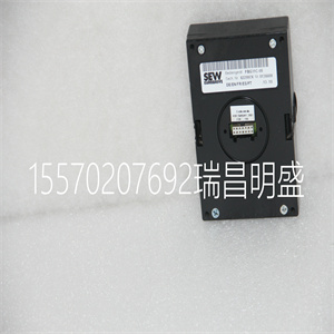
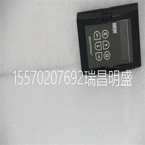
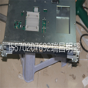


FBG31C-08
只需将您使用的编码器的引线与编码器匹配即可
互连板上的反馈输入。信号引线标记为CHA(信道
A) ,CHB(信道B)和索引。对于差分编码器,补码信号为:
标记为CHA-、CHB-和索引-。
注:当使用脉冲和方向编码器时,脉冲信号连接到CHA
并且方向信号连接到CHB。控制器必须配置为:
使用命令CE确定脉冲和方向。有关详细信息,请参见命令摘要
关于命令CE的信息。
步骤D.验证编码器操作是否正确。
首先从X编码器开始。连接后,转动电机轴并询问
带有指令TPX<return>的位置。控制器响应将随时间而变化
电机转动。
Artisan技术集团-质量仪器…保证|(888)88-SOURCE| www.artistg.com
14● 第2章DMC-18x2的入门
此时,如果TPX不随编码器旋转而变化,则有三种可能性:
1.编码器连接不正确-必要时检查接线。
2.编码器出现故障-使用示波器观察编码器信号。验证
信道A和B的峰值幅度都在5伏和12伏之间。笔记
如果只有一个编码器通道出现故障,位置报告将改变一个计数
只有如果编码器出现故障,请更换编码器。如果不能观察编码器
信号,尝试不同的编码器。
3.控制器中存在硬件故障-将同一编码器连接到其他编码器
轴如果问题消失,则可能是硬件故障。咨询
工厂寻求帮助。
步骤E.连接霍尔传感器(如果可用)。
霍尔传感器仅用于正弦换向,不需要进行适当的调整
活动霍尔传感器的使用允许控制器自动估计温度
复位时的换向阶段,并且还为控制器提供了设置更高频率的能力
确换向相位。如果没有霍尔传感器,换向相位必须为:
手动确定。
每组传感器必须使用连续顺序的输入。输入线是
用命令BI指定。例如如果Z轴的霍尔传感器为
连接到输入6、7和8,使用以下指令:
BI,6
或
BIZ=6
步骤8a。连接标准伺服电机
以下讨论适用于将DMC-18x2控制器连接到标准伺服电机
放大器:
马达和放大器可配置为扭矩或速度模式。在扭矩中
在模式下,放大器增益应使10伏信号产生所需的大电流。
在速度模式下,10伏的指令信号应以所需的大值运行电机
速度
WSDK(Windows伺服设计)中还包括伺服系统设置的逐步说明
套件)由Galil提供的软件。有关更多详细信息,请参见WSDK一节。
步骤A.检查反馈回路的极性
假设电机和放大器连接在一起,编码器为
正确操作(步骤B)。在将电机放大器连接到控制器之前,
阅读以下关于设置误差限制和扭矩限制的讨论。注意
讨论仅使用X轴作为示例。
步骤B.设置错误限制作为安全预防措施
通常,反馈的正确极性存在不确定性。错
极性使电机从起动位置跑开。使用终端
对于程序,如DMCTERM,可以给出以下参数以避免系统故障
损坏:
输入命令:
ER 2000<CR>将X轴上的误差限制设置为2000个编码器计数
当存在过大位置误差时,OE 1<CR>禁用X轴放大器
Artisan技术集团-质量仪器…保证|(888)88-SOURCE| www.artistg.com
DMC-18x2第2章入门•15
如果电机跑偏并产生2000个计数的位置误差,则电机放大器
将被禁用。注:此功能要求AEN信号从
控制器连接到放大器。
步骤C.设置扭矩限制作为安全预防措施
为了限制放大器的大电压信号,DMC-18x2控制器具有:
扭矩限制命令,TL。该命令设置电机的大电压输出
控制器,可用于在初始设置扭矩传感器时避免扭矩或速度过大
伺服系统。
当在扭矩模式下操作放大器时,控制器的电压输出将为:
与电机的扭矩输出直接相关。用户负责确定
该关系使用电机和放大器的文档。扭矩极限
可以设置为限制电机输出扭矩的值。
当在速度或电压模式下操作放大器时
控制器将与电机的速度直接相关。用户负责:
使用生产任务单文档确定这种关系
FBG31C-08

FBG31C-08
simply match the leads from the encoder you are using to the encoder feedback inputs on the interconnect board. The signal leads are labeled CHA (channel A), CHB (channel B), and INDEX. For differential encoders, the complement signals are labeled CHA-, CHB-, and INDEX-. Note: When using pulse and direction encoders, the pulse signal is connected to CHA and the direction signal is connected to CHB. The controller must be configured for pulse and direction with the command CE. See the command summary for further information on the command CE. Step D. Verify proper encoder operation. Start with the X encoder first. Once it is connected, turn the motor shaft and interrogate the position with the instruction TPX . The controller response will vary as the motor is turned. Artisan Technology Group - Quality Instrumentation ... Guaranteed | (888) 88-SOURCE | www.artisantg.com 14 ● Chapter 2 Getting Started DMC-18x2 At this point, if TPX does not vary with encoder rotation, there are three possibilities: 1. The encoder connections are incorrect - check the wiring as necessary. 2. The encoder has failed - using an oscilloscope, observe the encoder signals. Verify that both channels A and B have a peak magnitude between 5 and 12 volts. Note that if only one encoder channel fails, the position reporting varies by one count only. If the encoder failed, replace the encoder. If you cannot observe the encoder signals, try a different encoder. 3. There is a hardware failure in the controller - connect the same encoder to a different axis. If the problem disappears, you probably have a hardware failure. Consult the factory for help. Step E. Connect Hall Sensors if available. Hall sensors are only used with sinusoidal commutation and are not necessary for proper operation. The use of hall sensors allows the controller to automatically estimate the commutation phase upon reset and also provides the controller the ability to set a more precise commutation phase. Without hall sensors, the commutation phase must be determined manually. Each set of sensors must use inputs that are in consecutive order. The input lines are specified with the command, BI. For example, if the Hall sensors of the Z axis are connected to inputs 6, 7 and 8, use the instruction: BI ,, 6 or BIZ = 6 Step 8a. Connect Standard Servo Motors The following discussion applies to connecting the DMC-18x2 controller to standard servo motor amplifiers: The motor and the amplifier may be configured in the torque or the velocity mode. In the torque mode, the amplifier gain should be such that a 10 Volt signal generates the maximum required current. In the velocity mode, a command signal of 10 Volts should run the motor at the maximum required speed. Step by step directions on servo system setup are also included on the WSDK (Windows Servo Design Kit) software offered by Galil. See section on WSDK for more details. Step A. Check the Polarity of the Feedback Loop It is assumed that the motor and amplifier are connected together and that the encoder is operating correctly (Step B). Before connecting the motor amplifiers to the controller, read the following discussion on setting Error Limits and Torque Limits. Note that this discussion only uses the X axis as an example. Step B. Set the Error Limit as a Safety Precaution Usually, there is uncertainty about the correct polarity of the feedback. The wrong polarity causes the motor to run away from the starting position. Using a terminal program, such as DMCTERM, the following parameters can be given to avoid system damage: Input the commands: ER 2000 Sets error limit on the X axis to be 2000 encoder counts OE 1 Disables X axis amplifier when excess position error exists Artisan Technology Group - Quality Instrumentation ... Guaranteed | (888) 88-SOURCE | www.artisantg.com DMC-18x2 Chapter 2 Getting Started • 15 If the motor runs away and creates a position error of 2000 counts, the motor amplifier will be disabled. Note: This function requires the AEN signal to be connected from the controller to the amplifier. Step C. Set Torque Limit as a Safety Precaution To limit the maximum voltage signal to your amplifier, the DMC-18x2 controller has a torque limit command, TL. This command sets the maximum voltage output of the controller and can be used to avoid excessive torque or speed when initially setting up a servo system. When operating an amplifier in torque mode, the voltage output of the controller will be directly related to the torque output of the motor. The user is responsible for determining this relationship using the documentation of the motor and amplifier. The torque limit can be set to a value that will limit the output torque of the motor. When operating an amplifier in velocity or voltage mode, the voltage output of the controller will be directly related to the velocity of the motor. The user is responsible for determining this relationship using the documentation of the motor and amplifier. The torque limit can be set to a value that will limit the speed of the motor. For example, the following command will limit the output of the controller to 1 volt on the X axis: TL 1 Note: Once the correct polarity of the feedback loop has been determined, the torque limit should, in general, be increased to the default value of 9.99. The servo will not operate properly if the torque limit is below the normal operating range. See description of TL in the command reference
Copyright ©2019-2022 瑞昌明盛自动化设备有限公司 版权所有 赣ICP备2021006016号


