
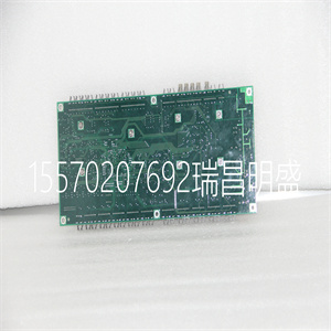
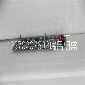
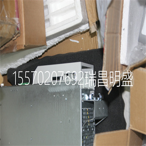
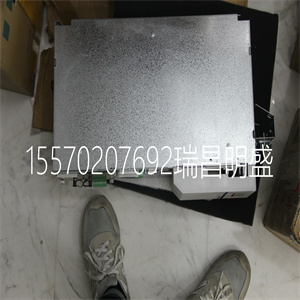


HDZ-70-30 B65W DC220V
随着比例增益的增加,误差减小。
同样,如果增益过高,系统可能会振动。在这种情况下,降低KP。通常,KP应:
不大于KD/4。(仅当放大器配置为电流模式时)。
后,要选择KI,从零值开始,然后逐渐增加。积分器消除了噪声
位置误差,从而提高精度。因此
TE X(CR)
变成零。随着KI的增加,其效应被放大,并可能导致振动。如果发生这种情况,
简单地减少KI。对Y、Z和W轴重复调谐。
有关PID滤波器和/或伺服系统理论操作的更详细说明,请参阅
10章-操作理论。
设计实例
下面是一些调整和使用控制器的示例。这些例子旁边有注释
每个命令-这些注释不得包含在实际程序中。
示例1-系统设置
此示例指定系统过滤器参数、误差限制并启用自动误差关闭。
指令解释
KP10,10,10,10设置a、b、c、d(或X、Y、Z、W轴)的增益
KP*=10用于设置所有轴增益的替代方法
KPX=10设置X(或A)轴增益的替代方法
KPA=10设置A(或X)轴增益的替代方法
KP,20只设置Y轴增益
ER*=1000将所有轴的误差限制设置为1000个计数
OE1,1,1.1启用所有4个轴的自动关闭-开启错误功能
示例2–轮廓移动
目标:以20000个计数/秒的回转速度将X轴旋转10000个计数的距离
加速和减速率为100000次/s2
在本例中,电机转动并停止:
指令解释
PR10000距离
SP20000速度
AC100000加速度
DC100000减速
BGX启动动作
示例3–多轴
目标:独立移动四个轴。
Artisan技术集团-质量仪器…保证|(888)88-SOURCE| www.artistg.com
DMC-18x22章入门•23
指令解释
PR 5001000600,-400 X,Y,Z,W的距离
SP 1000010002000010000 X、Y、Z、W的回转速度
AC 10000100001000010000100000 X,Y,Z,W的加速度
DC 800000400003000050000 X、Y、Z、W减速
BG XZ开始X和Z运动
BG YW开始Y和W运动
示例4-独立移动
运动参数可以独立地指定,如下所示。
指令解释
PR,Y和Z的300,-600距离
SP,2000 Y的回转速度
DC,Y减速80000
AC,100000 Y加速度
SP,40000 Z的回转速度
AC,100000 Z加速度
DC,Z减速150000
BG Z开始Z运动
BG Y开始Y运动
示例5-位置询问
可以用指令TP询问四个轴的位置。
指令解释
TP告知所有四个轴的位置
TP X告诉位置-仅X轴
TP Y告诉位置-仅Y轴
TP Z告诉位置-仅Z轴
TP W告知位置-仅限W轴
位置误差,即指令位置和实际位置之间的差值
可以用指令TE询问。
指令解释
TE告诉错误-所有轴
TE X告诉错误-仅X轴
TE Y告诉错误-仅Y轴
TE Z告诉错误-仅Z轴
TE W Tell error-W轴仅准确响应,如下所示:
演示提出了一种简单易行的补偿方法。更先进的设计方法是:
可使用Galil的软件设计工具,如伺服设计工具包(SDK软件)
该滤波器有三个参数:阻尼,KD;比例增益KP;和积分器KI。
应按此顺序选择参数。
首先,使用指令将积分器设置为零
KI 0(CR)积分器增益
并将比例增益设置为低值
KP 1(CR)比例增益
KD 100(CR)导数增益
为了获得更大的阻尼,您可以增加KD(大值为4095)。逐渐增加,然后停止
马达振动。振动可以通过声音或询问来察觉。如果您发送命令
TE X(CR)告诉错误
几次,得到不同的响应,特别是极性反转时,表示系统振动。
发生这种情况时,只需减少KD。
接下来,需要逐渐增加KP的值(允许的大值为1023)。您可以监视
使用Tell Error指令改善响应
KP 10(CR)比例增益
Artisan技术集团-质量仪器…保证|(888)
HDZ-70-30 B65W DC220V
HDZ-70-30 B65W DC220V
As the proportional gain is increased, the error decreases.
Again, the system may vibrate if the gain is too high. In this case, reduce KP. Typically, KP should
not be greater than KD/4. (Only when the amplifier is configured in the current mode).
Finally, to select KI, start with zero value and increase it gradually. The integrator eliminates the
position error, resulting in improved accuracy. Therefore, the response to the instruction
TE X (CR)
becomes zero. As KI is increased, its effect is amplified and it may lead to vibrations. If this occurs,
simply reduce KI. Repeat tuning for the Y, Z and W axes.
For a more detailed description of the operation of the PID filter and/or servo system theory, see
Chapter 10 - Theory of Operation.
Design Examples
Here are a few examples for tuning and using your controller. These examples have remarks next to
each command - these remarks must not be included in the actual program.
Example 1 - System Set-up
This example assigns the system filter parameters, error limits and enables the automatic error shut-off.
Instruction Interpretation
KP10,10,10,10 Set gains for a,b,c,d (or X,Y,Z,W axes)
KP*=10 Alternate method for setting gain on all axes
KPX=10 Alternate method for setting X (or A) axis gain
KPA=10 Alternate method for setting A (or X) axis gain
KP, 20 Set Y axis gain only
ER*=1000 Set error limit for all axes to 1000 counts
OE1,1,1,1 Enable automatic off on error function for all 4 axes
Example 2 – Profiled Move
Objective: Rotate the X axis a distance of 10,000 counts at a slew speed of 20,000 counts/sec and
acceleration and deceleration rates of 100,000 counts/s2
. In this example, the motor turns and stops:
Instruction Interpretation
PR10000 Distance
SP20000 Speed
AC100000 Acceleration
DC100000 Deceleration
BGX Start Motion
Example 3 – Multiple Axes
Objective: Move the four axes independently.
Artisan Technology Group - Quality Instrumentation ... Guaranteed | (888) 88-SOURCE | www.artisantg.com
DMC-18x2 Chapter 2 Getting Started • 23
Instruction Interpretation
PR 500,1000,600,-400 Distances of X,Y,Z,W
SP 10000,12000,20000,10000 Slew speeds of X,Y,Z,W
AC 100000,10000,100000,100000 Accelerations of X,Y,Z,W
DC 80000,40000,30000,50000 Decelerations of X,Y,Z,W
BG XZ Start X and Z motion
BG YW Start Y and W motion
Example 4 - Independent Moves
The motion parameters may be specified independently as illustrated below.
Instruction Interpretation
PR ,300,-600 Distances of Y and Z
SP ,2000 Slew speed of Y
DC ,80000 Deceleration of Y
AC, 100000 Acceleration of Y
SP ,,40000 Slew speed of Z
AC ,,100000 Acceleration of Z
DC ,,150000 Deceleration of Z
BG Z Start Z motion
BG Y Start Y motion
Example 5 - Position Interrogation
The position of the four axes may be interrogated with the instruction, TP.
Instruction Interpretation
TP Tell position all four axes
TP X Tell position - X axis only
TP Y Tell position - Y axis only
TP Z Tell position - Z axis only
TP W Tell position - W axis only
The position error, which is the difference between the commanded position and the actual position
can be interrogated with the instruction TE.
Instruction Interpretation
TE Tell error - all axes
TE X Tell error - X axis only
TE Y Tell error - Y axis only
TE Z Tell error - Z axis only
TE W Tell error - W axis only accurate response and the following
presentation suggests a simple and easy way for compensation. More advanced design methods are
available with software design tools from Galil, such as the Servo Design Kit (SDK software)
The filter has three parameters: the damping, KD; the proportional gain, KP; and the integrator, KI.
The parameters should be selected in this order.
To start, set the integrator to zero with the instruction
KI 0 (CR) Integrator gain
and set the proportional gain to a low value, such as
KP 1 (CR) Proportional gain
KD 100 (CR) Derivative gain
For more damping, you can increase KD (maximum is 4095). Increase gradually and stop after the
motor vibrates. A vibration is noticed by audible sound or by interrogation. If you send the command
TE X (CR) Tell error
a few times, and get varying responses, especially with reversing polarity, it indicates system vibration.
When this happens, simply reduce KD.
Next you need to increase the value of KP gradually (maximum allowed is 1023). You can monitor the
improvement in the response with the Tell Error instruction
KP 10 (CR) Proportion gain
Artisan Technology Group - Quality Instrumentation ... Guaranteed | (888)
Copyright ©2019-2022 瑞昌明盛自动化设备有限公司 版权所有 赣ICP备2021006016号


