


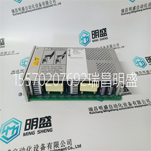
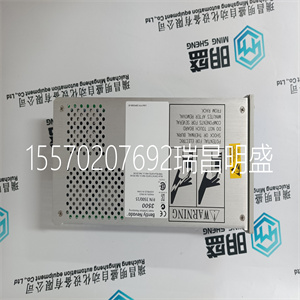


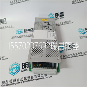
BENTLY 350015 127610-01
安装控制电缆的电缆夹。(输入:
图中未显示电源和电机电缆)。
2.剥去控制电缆护套。
1.
60.安装驱动器
ACH550-01用户手册
3.将控制电缆穿过夹具并拧紧
夹具。
4.连接数字和模拟I的接地(接地)屏蔽/
O X1:1的电缆。
5.将单独的控制线剥开并连接到驱动器上
终端。请参阅“应用程序宏和连接”一章。
6.安装接线盒盖(一个螺钉)。
警告!连接到的所有ELV(超低电压)电路
驱动器必须在等电位连接区域内使用,即:。
在所有可同时触及的导电部件所在的区域内
电气连接以防止出现危险电压
在他们之间。这是通过正确的工厂接地实现的。
要完成连接,请转至“应用”一章
宏和布线。
3.
4.
5.
收紧
扭矩:
0.4牛·米(0.3磅·英尺)
安装驱动器61
ACH550-01用户手册
检查安装
检查
已根据安装检查表完成安装准备工作。
驱动器安装牢固。
驱动器周围的空间与驱动器的
冷却技术规范(适当安装
第23页上的位置)。
电机和驱动设备已准备就绪
开始
对于IT系统,角接地TN系统
和剩余电流断路器:断开内部EMC滤波器(第43页,概述,布线安装概述(R1…R4))
第44页的布线安装(R5…R6)说明)。
驱动器正确接地。
输入电源(干线)电压与
驱动器的标称输入电压。
U1、V1处的输入电源(干线)连接
和W1按照规定连接和紧固。
输入电源(干线)保险丝和干线
安装了开关。(输入电源(干线)
第401页上的电缆、保险丝和断路器)。
U2、V2和W2处的电机连接为:
按规定连接并拧紧。
电机电缆远离其他电缆
电缆。
不使用功率因数补偿电容器
在马达电缆中。
控制连接被连接
按规定拧紧。
62.安装驱动器
ACH550-01用户手册
驱动器内没有工具或异物(如钻屑)。
电机无备用电源(例如
作为旁路连接)连接-不向驱动器的输出施加电压。
BENTLY 350015 127610-01
BENTLY 350015 127610-01
Install the cable clamp(s) for the control cable(s). (Input power and motor cables are not shown in the figure). 2. Strip the control cable sheathing. 1 60 Installing the drive ACH550-01 User's Manual 3. Route the control cable(s) through the clamp(s) and tighten the clamp(s). 4. Connect the ground (earth) shield for digital and analogue I/ O cables at X1:1. 5. Strip and connect the individual control wires to the drive terminals. See chapter Application macros and wiring. 6. Install the connection box cover (one screw). WARNING! All ELV (Extra Low Voltage) circuits connected to the drive must be used within a zone of equipotential bonding, i.e. within a zone where all simultaneously accessible conductive parts are electrically connected to prevent hazardous voltages appearing between them. This is accomplished by a proper factory grounding. For completing the connections, go to chapter Application macros and wiring. 3 4 5 Tightening torque: 0.4 N·m (0.3 lb·ft) Installing the drive 61 ACH550-01 User's Manual Check installation Check The installation preparations have been completed according to the installation checklist. The drive is mounted securely. The space around the drive meets the drive’s specifications for cooling (Suitable mounting location on page 23). The motor and driven equipment are ready for start. For IT systems, corner-grounded TN systems and residual current circuit breakers: the internal EMC filter is disconnected (Overview of wiring installation (R1…R4) on page 43, Overview of wiring installation (R5…R6) on page 44). The drive is properly grounded. The input power (mains) voltage matches the drive’s nominal input voltage. The input power (mains) connections at U1, V1 and W1 are connected and tightened as specified. The input power (mains) fuses and mains switch are installed. (Input power (mains) cable, fuses and circuit breakers on page 401). The motor connections at U2, V2 and W2 are connected and tightened as specified. The motor cable is routed away from other cables. NO power factor compensation capacitors are in the motor cable. The control connections are connected and tightened as specified. 62 Installing the drive ACH550-01 User's Manual NO tools or foreign objects (such as drill shavings) are inside the drive. NO alternate power source for the motor (such as a bypass connection) is connected - no voltage is applied to the output of the drive.
Copyright ©2019-2022 瑞昌明盛自动化设备有限公司 版权所有 赣ICP备2021006016号


