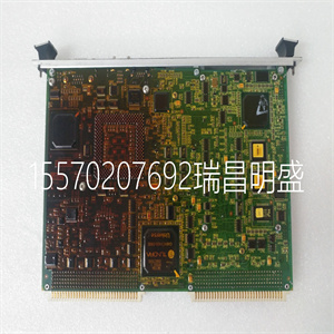


GE IS215UCVEM08B
此应用程序宏适用于速度参考
需要通过数字输入(DI5和DI6)进行控制。通过
激活数字输入5,速度参考值增加。通过
激活数字输入6,速度基准降低。如果两者都是
数字输入处于激活或非激活状态,参考不处于激活状态
改变
注:当使用数字输入3激活恒速1时
(DI3),参考速度是参数1202的值
当数字输入3被激活时,该值保持为参考速度
解散。
ACH550-01用户手册
应用程序宏和布线115
1个SCR信号电缆屏蔽(屏幕)
2.未使用AI1
3 AGND模拟输入电路公共
4 10V参考电压+10V直流电
5未使用AI2
6 AGND模拟输入电路公共
7 AO1输出频率:0(4)…20mA
8 AO2输出电流:0(4)…20mA
9 AGND模拟输出电路公共
10 24V辅助电压输出+24 V直流电
11 DI返回信号的接地公共线
12 DCOM数字输入通用于所有
13 DI1启动/停止:激活启动驱动器
14 DI2运行启用:停用将停止驱动2
15 DI3恒速1(1202段)1
16 DI4启动启用1:停用停止驱动器2
17 DI5基准向上:激活增加基准
18 DI6基准下降:激活降低基准
19 RO1C继电器输出1(1401段)
默认操作
已启动=>19连接到21
20 RO1A
21 RO1B
22 RO2C继电器输出2(1402段)
默认操作
运行=>22连接到24
23 RO2A
24 RO2B
25 RO3C继电器输出3(1403段)
默认操作
故障(-1)=>25连接到27
26 RO3A
27 RO3B
1如果激活PID,则不可用
2.使用参数1601和1608禁用/启用
注意:只有在可能的保护功能(运行启用或启动启用1和2)下,驱动器才会启动
2) 通过I/O激活或通过参数禁用。
浮点
ACH550-01用户手册
116应用程序宏和布线
11.双设定点PID
该应用宏用于双设定点PI(D)
过程PI(D)控制器设定值可以设置的应用
通过激活数字输入3(DI3)改变为另一个值。
过程PI(D)设置点在驱动器内部通过
参数4011(集合1)和4111(集合2)。
在自动模式下使用直接速度参考时
速度基准必须连接到模拟输入1(AI1)
并且用数字输入1(DI1)给出启动命令。在里面
切换/断开模式、速度参考和起动
通过控制面板(操作员键盘)发出命令。
如果使用过程PI(D)
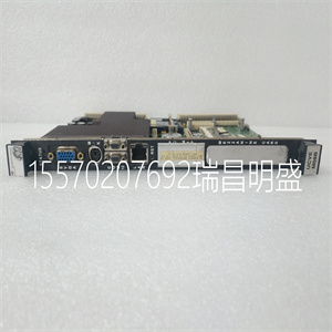
GE IS215UCVEM08B

GE IS215UCVEM08B
This application macro is for applications where speed reference needs to be controlled through digital inputs (DI5 and DI6). By activating digital input 5, the speed reference increases. By activating digital input 6, the speed reference decreases. If both digital inputs are active or inactive, the reference does not change. Note: When constant speed 1 is activated using digital input 3 (DI3), the reference speed is the value of parameter 1202. The value remains as the reference speed when digital input 3 is deactivated. ACH550-01 User's Manual Application macros and wiring 115 1 SCR Signal cable shield (screen) 2 AI1 Not used 3 AGND Analogue input circuit common 4 10V Reference voltage +10 V DC 5 AI2 Not used 6 AGND Analogue input circuit common 7 AO1 Output frequency: 0(4)…20 mA 8 AO2 Output current: 0(4)…20 mA 9 AGND Analogue output circuit common 10 24V Auxiliary voltage output +24 V DC 11 GND Common for DI return signals 12 DCOM Digital input common for all 13 DI1 Start/Stop: Activation starts the drive 14 DI2 Run enable: Deactivation stops the drive 2 15 DI3 Constant speed 1 (par. 1202) 1 16 DI4 Start enable 1: Deactivation stops the drive 2 17 DI5 Reference up: Activation increases the reference 18 DI6 Reference down: Activation decreases the reference 19 RO1C Relay output 1 (par. 1401) Default operation Started => 19 connected to 21 20 RO1A 21 RO1B 22 RO2C Relay output 2 (par. 1402) Default operation Running => 22 connected to 24 23 RO2A 24 RO2B 25 RO3C Relay output 3 (par. 1403) Default operation Fault (-1) => 25 connected to 27 26 RO3A 27 RO3B 1 Not available if PID is activated 2 Disable/enable with parameters 1601 and 1608 Note: The drive starts only if possible protection functions (Run enable or Start enable 1 and 2) are activated from I/O or disabled with parameters. Floating point ACH550-01 User's Manual 116 Application macros and wiring 11. Dual setpoint PID This application macro is intended for dual setpoint PI(D) applications where process PI(D) controllers setpoint can be changed to another value by activating digital input 3 (DI3). Process PI(D) setpoints are set to the drive internally with parameters 4011 (set 1) and 4111 (set 2). When using a direct speed reference in the AUTO mode, the speed reference must be connected to analogue input 1 (AI1) and the START command is given with digital input 1 (DI1). In the HAND/OFF mode, the speed reference and START command are given through the control panel (operator keypad). If process PI(D) is used, the fee
Copyright ©2019-2022 瑞昌明盛自动化设备有限公司 版权所有 赣ICP备2021006016号


