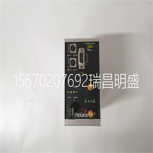


PROSOFT 6105-WA-PDPS
模块前面板上有六个模块状态指示灯:三个正常,一个正常
活动,一个备用,一个受教育。健康指标由以下人员直接控制:
每个模块都是一个切片。活动、备用和指示灯由FPU控制。
FPU从每个模块片接收数据。它对每个数据进行2O3表决
并相应地设置指示符。
模块状态指示器模式及其含义描述如下:
指示器状态描述
正常关闭:模块未通电。
琥珀色片处于启动状态(安装后瞬间
或通电)。
绿色切片是健康的。
红色–相关切片上存在闪烁故障,但切片仍然存在
操作的
安装时红色(瞬时)-施加到相关片的电源。
红色:关联切片处于致命状态。出现严重故障
已检测到并禁用切片。
主动关闭
绿色
红色–闪烁
红色–闪烁
模块未处于活动状态。
模块处于激活(或保持)状态。
如果备用LED熄灭,则模块处于关闭状态。
如果备用指示灯也亮起,则模块处于致命状态
闪烁。
待命
绿色
红色–闪烁
模块未处于待机状态。
模块处于待机状态。
模块处于致命状态。激活的LED也将被激活
闪烁着红色。
可信TMR 24Vdc数字输出模块–40信道4.运行
罗克韦尔自动化出版物ICSTT-RM280N-EN-P14和27期
指示器状态描述
受过教育
绿色
绿色–闪烁
琥珀色-闪烁
模块未受教育。
模块被教育。
处理器可以识别模块,但无法识别教育
这是不完整的。
正在进行主动/备用切换。
表16模块状态指示灯
4.3.输入/输出状态指示器
模块前面板上有40个输出通道状态指示器,每个字段一个
输出这些指示器由FPU控制。FPU接收来自每个处理器的数据
模块切片。FPU对来自切片的每个数据位执行2oo3表决,并设置
相应的指标。
输出状态指示器模式取决于输出的数值状态
频道每个输出状态可以定义为具有特定的指示器模式:关闭、绿色、蓝色和蓝色,
红色、闪烁的绿色或闪烁的红色。
可配置指示器模式允许用户自定义输出状态指示,以:
适合个人应用要求。如果没有自定义,默认指示器
模式适用于线路监控数字输出设备,如下所述:
PROSOFT 6105-WA-PDPS
PROSOFT 6105-WA-PDPS
There are six Module status indicators on the Module Front Panel: three Healthy, one Active, one Standby, and one Educated. The Healthy indicators are controlled directly by each Module slice. The Active, Standby, and Educated indicators are controlled by the FPU. The FPU receives data from each of the Module slices. It performs a 2oo3 vote on each data bit from the slices and sets the indicators accordingly. The Module status indicator modes and their meanings are described as follows: INDICATOR STATE DESCRIPTION Healthy Off No power applied to the Module. Amber Slice is in the start-up state (momentary after installation or power-up). Green Slice is healthy. Red – flashing Fault present on the associated slice but the slice is still operational. Red (momentary) On installation – power applied to the associated slice. Red The associated slice is in the fatal state. A critical fault has been detected and the slice disabled. Active Off Green Red – flashing Red – flashing Module is not in the Active state. Module is in the Active (or Maintain) state. Module is in the shutdown state if the Standby LED is off. Module is in the fatal state if the Standby LED is also flashing. Standby Off Green Red – flashing Module is not in the Standby state. Module is in the Standby state. Module is in the fatal state. The Active LED will also be flashing red. Trusted TMR 24Vdc Digital Output Module – 40 Channel 4. Operation Rockwell Automation Publication ICSTT-RM280N-EN-P Issue 14 27 INDICATOR STATE DESCRIPTION Educated Off Green Green – flashing Amber - Flashing Module is not educated. Module is educated. Module is recognised by the Processor but education is not complete. Active/Standby changeover in progress. Table 16 Module Status LEDs 4.3. I/O Status Indicators There are 40 output channel status indicators on the Module Front Panel, one for each field output. These indicators are controlled by the FPU. The FPU receives data from each of the Module slices. The FPU performs a 2oo3 vote on each data bit from the slices and sets the indicators accordingly. The output status indicator mode is dependent upon the numerical state of the output channel. Each output state can be defined to have a particular indicator mode: off, green, red, flashing green, or flashing red. The configurable indicator modes allow users to customise the output status indications to suit individual application requirements. Without customisation, the default indicator modes are suitable for line-monitored digital output devices as described below:
Copyright ©2019-2022 瑞昌明盛自动化设备有限公司 版权所有 赣ICP备2021006016号


