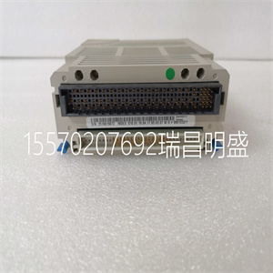

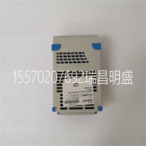
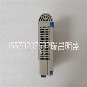
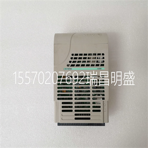


WESTINGHOUSE 1C31194G01
TPMC815上使用的COM20020 ARCNET控制器能够与不同的设备一起工作
CPU总线结构。COM20020设备通过监视一总线来学习所使用的总线结构
对COM20020寻址的周期。
要将COM20020 ARNET控制器初始化为正确的CPU总线结构,软件必须:
系统复位后,立即对COM20020进行以下访问:
1.在字节偏移量0x01处将0x55写入命令寄存器。
2.读取字节偏移量0x01处的诊断状态寄存器。
如果复位后,COM20020未按上述顺序初始化,则ARCNET
PMC将无法正常运行。
6.1.2时钟源
在TPMC815上,COM20020 ARCNET控制器配备40 MHz时钟。
6.1.3编程
有关COM20020 ARCNET控制器的编程,请参阅COM20020数据表。
TPMC815用户手册版本2.0.218页,共20页
7.安装说明
7.1车载ID开关
TPMC815提供了一个板载8 x dip开关。开关设置可通过以下位置的软件读取:
初始化时间,该值可用于编程COM20020 ARCNET的节点ID
控制器。
处于关闭位置的开关表示逻辑“1”,处于打开位置的开关代表逻辑“0”。
工厂配置:所有dip开关均设置在断开位置(表示字节值0xFF)。
7.2布线提示/网络布线
对于RS485网络,应使用阻抗为100欧姆@1 MHz的双绞线电缆。
它可以是AWG 22、24、26。
所有网络信号线必须在布线网络的两端端接一个电阻器
连接在信号+和信号之间. 电阻值应等于电阻器的阻抗
缆绳
RS485注释(TPMC815-21R):
TPMC815-21R提供可启用或禁用的板载RS485线路终端
通过跳投。
如果启用,板载RS485线路终端为:
隔离RS484信号之间的120R端接电阻器,隔离RS482信号之间的1K5偏置电阻器
隔离RS485信号+和隔离RS485电源(+5V)、1K5之间的偏置电阻器
隔离RS485信号和隔离RS485接地。
如果总线仅使用TPMC815模块构建,则总线端的两个TPMC81五模块
必须启用端接跳线,而其他TPMC815模块必须启用
终端跳线被禁用。
如果TPMC815模块与提供固定板载偏置的其他模块一起使用
对于电源端接,应禁用TPMC815端接跳线。在这种情况下
TPMC815模块应放置在总线端,并在总线之间使用外部总线终端
信号+和信号-。
TPMC815用户手册版本2.0.219页,共20页
7.3跳线配置
TPMC815-21R由跳线J3和J4配置。
J3和J4设置板载RS485线路终端模式。
如果启用,板载RS485线路终端为:
隔离RS484信号之间的120R端接电阻器,隔离RS482信号之间的1K5偏置电阻器
RS485信号+和隔离RS485电源(+5V),隔离RS485之间的1K5偏置电阻器
信号–和隔离RS485接地。
跳线功能安装选项
TPMC815-21R
J3、J4 RS485线路
终止模式
两个闭合的RS485线路终端均打开
断开RS485线路端接和断开
表7-1:跳线配置
图7-1:跳线位置
TPMC815用户手册版本2.0.220页,共20页
8针分配–I/O连接器
8.1 DB9前I/O连接器
Pin信号注释
1隔离RS485信号 TPMC815-21R
2隔离RS485信号 TPMC815-21R
3 N.C。
4 N.C。
5 N.C。
6隔离接地
7隔离接地
8 N.C。
9隔离接地
表8-1:销Assi
•展示学生作品。
•旨在促进个人和团体的发展
学习
教室:
•有点冷,不吸引人。
•组织不善,不易理解
学生。
•供应、设备和资源困难
访问。
•不显示学生作品。
•未安排促进小组学习。
恭敬的
文化
•师生互动展示关怀
相互尊重。
•学生表现出对他人的关心和尊重
另一个
•积极的关系和相互依存
描述教室的特征。
•师生互动通常是:
友好,但这可能反映出偶尔
不一致、偏袒或无视
学生的文化。
•学生表现出对老师的尊重,并且:
通常对彼此有礼貌。
•教师有时会接受学生的兴趣
以及学生的意见。
•师生互动有时会受到影响
专制的、消极的或不适当的。
•学生表现出对老师的不尊重。
•学生互动的特点是冲突,
挖苦,还是把陶氏
WESTINGHOUSE 1C31194G01
WESTINGHOUSE 1C31194G01
The COM20020 ARCNET Controller, which is used on the TPMC815, is able to work with different
CPU bus structures. The COM20020 device learns the used bus structure by monitoring the first bus
cycles which address the COM20020.
To initialize the COM20020 ARNET Controller to the right CPU bus structure the software must
do the following accesses to the COM20020 immediately after a system reset:
1. Write 0x55 to the Command Register at byte offset 0x01.
2. Read the Diagnostic Status Register at byte offset 0x01.
If after a reset, the COM20020 is not initialized with the sequence listed above, the ARCNET
PMC will not operate properly.
6.1.2 Clock Source
On the TPMC815 the COM20020 ARCNET Controller is sourced with a 40 MHz clock.
6.1.3 Programming
For programming the COM20020 ARCNET Controller please refer to the COM20020 data sheet.
TPMC815 User Manual Issue 2.0.2 Page 18 of 20
7 Installation Notes
7.1 On board ID Switch
The TPMC815 provides an on board 8 x dip-switches. The switch setting can be read by software at
initialization time where the value may be used to program the node ID of the COM20020 ARCNET
Controller.
A switch in position OFF represents a logical ‘1’, a switch in position ON represents a logical ‘0’.
Factory configuration: All dip-switches are set in OFF position (representing the byte value 0xFF).
7.2 Wiring Hints / Network Cabling
For an RS485 network a twisted pair cable with an impedance of 100ohms @ 1 MHz should be used.
It can be AWG 22, 24, 26.
All network signal lines must be terminated at both extremes of the cabling network with a resistor
connected between Signal+ and Signal. The resistor value should be equal to the impedance of the
cable.
RS485 Notes (TPMC815-21R):
The TPMC815-21R provides on board RS485 line termination which can be enabled or disabled
by jumpers.
If enabled, the on board RS485 line termination is:
120R termination resistor between the isolated RS484 Signals, 1K5 bias resistor between the
isolated RS485 Signal+ and the isolated RS485 supply (+5V), 1K5 bias resistor between the
isolated RS485 Signal– and isolated RS485 GND.
If the bus is build with TPMC815 modules only, the two TPMC815 modules at the bus ends
must have the termination jumpers enabled, while the other TPMC815 modules must have the
termination jumpers disabled.
If a TPMC815 module is used along with other modules that provide fix on board bias
termination to the supply, the TPMC815 termination jumpers should be disabled. In this case, if
a TPMC815 module should be placed at a bus end, use external bus termination between
Signal+ and Signal-.
TPMC815 User Manual Issue 2.0.2 Page 19 of 20
7.3 Jumper Configuration
The TPMC815-21R is configured by the jumpers J3 and J4.
J3 and J4 set the on board RS485 line termination mode.
If enabled, the on board RS485 line termination is:
120R termination resistor between the isolated RS484 Signals, 1K5 bias resistor between the isolated
RS485 Signal+ and the isolated RS485 supply (+5V), 1K5 bias resistor between the isolated RS485
Signal– and isolated RS485 GND.
Jumper Function Installation Option
TPMC815-21R
J3, J4 RS485 Line
Termination Mode
Both Closed RS485 Line Termination ON
Both Open RS485 Line Termination OFF
Table 7-1 : Jumper Configuration
Figure 7-1 : Jumper Location
TPMC815 User Manual Issue 2.0.2 Page 20 of 20
8 Pin Assignment – I/O Connector
8.1 DB9 Front I/O Connector
Pin Signal Comment
1 Isolated RS485 Signal TPMC815-21R
2 Isolated RS485 Signal TPMC815-21R
3 N.C.
4 N.C.
5 N.C.
6 Isolated GND
7 Isolated GND
8 N.C.
9 Isolated GND
Table 8-1 : Pin Assi
• displays student work.
• is arranged to promote individual and group
learning.
The classroom:
• is somewhat cold and uninviting.
• is not well organized and understandable to
students.
• supplies, equipment, and resources are difficult
to access.
• does not display student work.
• is not arrange to promote group learning.
Respectful
Culture
• Teacher-student interactions demonstrate caring
and respect for one another.
• Students exhibit caring and respect for one
another.
• Positive relationships and interdependence
characterize the classroom.
• Teacher-student interactions are generally
friendly, but may reflect occasional
inconsistencies, favoritism, or disregard for
students’ cultures.
• Students exhibit respect for the teacher, and are
generally polite to each other.
• Teacher is sometimes receptive to the interests
and opinions of students.
• Teacher-student interactions are sometimes
authoritarian, negative, or inappropriate.
• Students exhibit disrespect for the teacher.
• Student interaction is characterized by conflict,
sarcasm, or put-dow
Copyright ©2019-2022 瑞昌明盛自动化设备有限公司 版权所有 赣ICP备2021006016号


