

Woodward 8226-043
在许多涡轮机中,希望避免某些速度或速度范围(或通过
尽可能快地穿过它们),因为涡轮机过度振动或其他
因素。在编程期间,两个临界速度避免带可能为
挑选出来的。这些频带可以是小于小值的任何速度范围
调速器速度设置。怠速/额定或自动启动顺序
必须对功能进行编程,以避免临界速度。在一个
临界速度范围,505以临界速度速率移动速度设定点
已编程,不允许速度设定点在临界范围内停止
速度回避带。如果涡轮机加速通过临界避让
遇到频带和过高振动,选择速度
设定点下限命令将使装置回到带的下限。
505数字调速器手册85017V1
12伍德沃德
方框图
图1-5至图1-7显示了可能的505配置概览。
使用这些方框图将控制功能与特定站点相匹配
应用要求。图1-4列出了符号及其各自的
解释。级联和辅助PID是可选控制器,并且
下图所示仅用于PID关系。
图1-4.505功能注释概述
手动85017V1 505数字调速器
伍德沃德13
涡轮转速
促动器
限制器
阀门
LSS
速度
设定点
驾驶员1
缩放驱动程序2
促动器
缩放比例
提高
降低
遥远的
输入
使能
输入
855−668
(4−20mA)
02−12−31
图1-5.单量程或分程涡轮机配置
(带远程设定点的速度PID)
涡轮转速
辅助输入
促动器
限制器
阀门
LSS
级联输入
卡斯克
下垂
设定点
设定点
设定值百分比
转/分
转换
启用联络断路器下垂
发电机断路器
启用级联
驾驶员1
驱动程序2
促动器
缩放比例
KW/单位负荷
855−669
速度
辅助的
缩放比例
逻辑
02−12−31
图1-6.单量程或分量程涡轮机配置
(辅助PID配置为限制器)
505数字调速器手册85017V1
14伍德沃德
涡轮转速
促动器
限制器
阀门
级联输入LSS
卡斯克
下垂
设定点
设定点百分比
转/分
转换
使能
连接断路器下垂
发电机断路器
启用级联
C
使能
辅助控制
缩放比例
驱动程序1
促动器
驾驶员2
跟踪
KW/单位负荷
缩放比例
855−670
速度
辅助输入
设定点
辅助的
逻辑
02−12−31
图1-7.单量程或分程涡轮机配置
(配置为控制器的辅助PID)
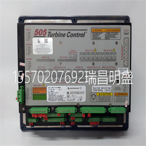
键盘和显示器
505的维修面板由位于上的键盘和LED显示屏组成
控件的前面。LED显示屏有两行24个字符,可以使用
以纯英语显示操作参数和故障排除参数。
此外,有30个键可用于从
505.不需要额外的控制面板来操作涡轮机,每个
涡轮机控制功能可从505的前面板执行。
图1-8.505键盘和显示器
手动85017V1 505数字调速器
伍德沃德15
每个键的功能描述如下。一些描述涉及
编程(第4章)和操作手册中包含的功能块
流程图(第5章)。
纸卷:
键盘中间的大菱形按钮,每个按钮上都有箭头
当然是四个角。<>(向左、向右滚动)将显示屏向左或向右移动
程序或运行模式的功能块。{},}(向上、向下滚动)
在程序或运行模式的功能块内向上或向下移动显示器。
选择:
选择键用于选择控制505显示屏的顶行或底行
变量@符号用于指示可通过以下方式调整的行(变量):
调整键。仅当两行上都有可变变量时
(动态、阀门校准模式)“选择键”和@符号是否确定
该线变量可以被调整。当每个屏幕只有一个变量时
“选择键”和@sign的位置无关。
调整:
在运行模式下,“Ϩ”将任何可调参数向上移动(较大),而“Ϩ将移动
任何可调参数向下(或更小)。
PRGM(项目):
当控制装置关闭时,此键选择编程模式。在
运行模式此键选择程序监视器模式。在程序监视器中
模式可以查看程序,但不能更改。
运行:
从(控制)启动涡轮机运行或启动命令
参数/推送运行或PRGM)状态。
停止:
验证完成后,启动受控汽轮机停机(运行模式)。“停止”
命令可以通过S禁用
Woodward 8226-043

Woodward 8226-043
In many turbines, it is desirable to avoid certain speeds or speed ranges (or pass through them as quickly as possible) due to excessive turbine vibration or other factors. During programming, two critical speed avoidance bands may be selected. These bands may be any speed ranges that is less than the minimum governor speed setting. Either the Idle/Rated or the Auto Start Sequence functions must be programmed to perform critical speed avoidance. Within a critical speed range, the 505 moves the speed setpoint at the critical speed rate programmed and does not allow the speed setpoint to stop within the critical speed avoidance band. If the turbine is accelerating through a critical avoidance band and excessively high vibrations are experienced, selecting the speed setpoint lower command will bring the unit back to the lower limit of the band. 505 Digital Governor Manual 85017V1 12 Woodward Block Diagrams Overviews of possible 505 configurations are shown in Figures 1-5 through 1-7. Use these block diagrams to match the control features to the site-specific application requirements. Figure 1-4 lists symbols and their respective explanations. The Cascade and auxiliary PIDs are optional controllers, and are shown in the following diagrams for PID relationship purposes only. Figure 1-4. Overview of 505 Functionality Notes Manual 85017V1 505 Digital Governor Woodward 13 TURBINE SPEED ACTUATOR LIMITER VALVE LSS SPEED SETPOINT DRIVER 1 SCALING DRIVER 2 ACTUATOR SCALING RAISE LOWER REMOTE INPUT ENABLE INPUT 855−668 (4−20mA) 02−12−31 Figure 1-5. Single or Split-Range Turbine Configurations (Speed PID with Remote Setpoint) TURBINE SPEED AUXILIARY INPUT ACTUATOR LIMITER VALVE LSS CASCADE INPUT CASC DROOP SETPOINT SETPOINT SETPOINT PERCENT TO RPM CONVERSION ENABLE TIE BREAKER DROOP GEN BREAKER ENABLE CASCADE DRIVER 1 DRIVER 2 ACTUATOR SCALING KW/UNIT LOAD 855−669 SPEED AUX SCALING LOGIC 02−12−31 Figure 1-6. Single or Split-Range Turbine Configurations (Auxiliary PID Configured as a Limiter) 505 Digital Governor Manual 85017V1 14 Woodward TURBINE SPEED ACTUATOR LIMITER VALVE CASCADE INPUT LSS CASC DROOP SETPOINT SETPOINT PERCENT TO RPM CONVERSION ENABLE TIE BREAKER DROOP GEN BREAKER ENABLE CASCADE C ENABLE AUX CONTROL SCALING DRIVER 1 ACTUATOR DRIVER 2 TRACKING KW/UNIT LOAD SCALING 855−670 SPEED AUXILIARY INPUT SETPOINT AUX LOGIC 02−12−31 Figure 1-7. Single or Split-Range Turbine Configurations (Auxiliary PID Configured as a Controller) Keypad and Display The 505’s service panel consists of a keypad and LED display located on the front of the control. The LED display has two, 24 character lines that can be used to display operating parameters and troubleshooting parameters in plain English. Also, there are 30 keys available to provide complete control from the front of the 505. No additional control panels are required to operate the turbine, every turbine control function can be performed from the 505’s front panel. Figure 1-8. 505 Key Pad and Display Manual 85017V1 505 Digital Governor Woodward 15 A description of each key’s function follows. Some descriptions refer to the function blocks contained in the programming (Chapter 4) and operating flowcharts (Chapter 5). SCROLL : The large diamond shaped button in the middle of the keypad with arrows at each of it’s four corners. The < > (scroll left, right) moves the display left or right through the function blocks of the Program or Run Mode. The , (scroll up, down) moves the display up or down within a function block of the Program or Run Mode. SELECT: The Select key is used to select control of the 505 display’s top or bottom line variable. The @ sign is used to indicate which line (variable) can be adjusted by the adjust keys. Only when there is a changeable variable on both lines (dynamics, valve calibration modes) does the “select key” and @ sign determine which line variable can be adjusted. When there is only one variable per screen the “select key” and @ sign’s position are irrelevant. ADJ (adjust): In the Run Mode, “ “ moves any adjustable parameter up (larger) and “ “ moves any adjustable parameter down (smaller). PRGM (program): When the control is shutdown this key selects the Program Mode. While in the Run Mode this key selects a Program Monitor Mode. In the Program Monitor Mode the program can be viewed but not changed. RUN: Initiates a turbine run or start command from the (CONTROLLING PARAMETER/PUSH RUN or PRGM) state. STOP: Initiates a controlled turbine shutdown (Run Mode) once verification is given. The “Stop” command can be disabled through a S
Copyright ©2019-2022 瑞昌明盛自动化设备有限公司 版权所有 赣ICP备2021006016号


