
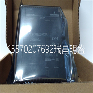


5X00031H01
(六角)导线类型
临时雇员
属于
临时雇员
oC
冷电阻
(欧姆)
罗特
(欧姆)
激发
现在的
(马)
确
±
±计数
确
百分之±
跨度
1 3 10欧姆
PL
0至
1200
–18至
649
6 106.3 0.1556 9 0.22
2、3、10欧姆
铜
0至
302
–18至
150
8.5 16.5 1.51 13 0.32
D350欧姆
铜
32至
284
0至
140
50 80 1.0756 11 0.27
11 3 50欧姆
铜
32至
230
0至
110
53 78 1.1291 12 0.30
19 3 100
欧姆PL
–4至
334
–16至
168
92 163.6
7.
0.5121 11 0.27
22 3 100
欧姆PL
32至
520
0至
269
100 200 0.4087 10 0.25
23 3 100
欧姆PL
32至
1040
0至
561
100 301 0.2554 10 0.25
25 3 120
欧姆镍
12至
464
–11至
240
109 360 0.2104 10 0.25
26 3 120
欧姆镍
32至
150
0至
70
120 170 0.5240 13 0.32
28 3 120
欧姆镍
32至
278
0至
122
120 225 0.3682 11 0.27
80 4 100
欧姆PL
32至
544
0至
290
100 208 0.3921 10 0.25
81 4 100
欧姆PL
356至
446
180至
230
168 186 0.5240 30 0.74
82 4 200
欧姆PL
32至
698
0至
370
200 473 0.1675 12 0.30
83 4 200
欧姆PL
514至
648
268至
342
402 452 0.2142 29 0.71
84 4 100
欧姆PL
32至
124
0至
51
100 120 0.7860 19 0.47
85 4 100
欧姆PL
32至
217
0至
103
100 140 0.6386 13 0.32
86 4 100
欧姆PL
32至
412
0至
211
100 180 0.4644 11 0.27
87 4 100
欧姆PL
32至
714
0至
379
100 240 0.3296 10 0.25
88 4 120
欧姆PL
511至
662
266至
350
200 230 0.4170 24 0.59
14 IPU-247
艾默生过程管理专有2C类
在第22节中添加以下更改:
第22-2页,在第二段之后添加以下信息(双通道…序列)
第22-2节(操作):
从版本0C开始,RSR固件支持级联PI配置,其中
PI 1的输出用作PI 2的目标位置输入
级联操作是选择直接/间接PI操作的标志,以及反饱和操作
这一功能被称为“撤退”。这些新特征中的一些实际上独立于级联,
但所有这些都在本文档中详细描述。
第22-9页,删除第二段(任意)之后的所有剩余段落(六段)
限制…10.0伏。)在校准模式部分下的完整校准项目符号中:
第22-9页,添加以下信息,以取代上述项目中删除的段落:
当要求完全校准时,阀门首先移动至0%。0%时,解调器增益为
直到反馈电压接近10伏。此时的解调器增益为:
大可能解调器增益。
则阀门移动到100%。如果电压大于10伏或偏离刻度,
降低解调器增益,并读取电压。这个读数是
100%校准阀。
然后阀门移动到0%,并读取电压读数。该读数为0%
校准值。
确定0%校准阀后,将新值写入EE存储器。
第22-17页,在第22-8节(阀位控制)下,将“阀座和
后座”与以下内容:
22-8.1座位、后座和后退
座椅和后座功能相似,但座椅关闭
阀门,后座打开阀门。因此,仅描述了座椅。
撤退是一种反饱和功能。重要的是要记住,当RSR伺服
输出接近0伏,阀门处于静止状态。当伺服输出从
中点,阀门移动到所需位置,伺服输出返回到near
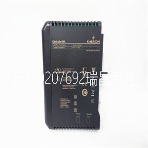
5X00031H01
5X00031H01
(HEX) Wires Type Temp oF Temp oC Rcold (ohm) Rhot (ohm) Excitation current (ma) Accuracy ± ±counts Accuracy ± ±% of SPAN 1 3 10 Ohm PL 0 to 1200 –18 to 649 6 106.3 0.1556 9 0.22 2 3 10 Ohm CU 0 to 302 –18 to 150 8.5 16.5 1.51 13 0.32 D 3 50 Ohm CU 32 to 284 0 to 140 50 80 1.0756 11 0.27 11 3 50 Ohm CU 32 to 230 0 to 110 53 78 1.1291 12 0.30 19 3 100 Ohm PL –4 to 334 –16 to 168 92 163.6 7 0.5121 11 0.27 22 3 100 Ohm PL 32 to 520 0 to 269 100 200 0.4087 10 0.25 23 3 100 Ohm PL 32 to 1040 0 to 561 100 301 0.2554 10 0.25 25 3 120 Ohm NI 12 to 464 –11 to 240 109 360 0.2104 10 0.25 26 3 120 Ohm NI 32 to 150 0 to 70 120 170 0.5240 13 0.32 28 3 120 Ohm NI 32 to 278 0 to 122 120 225 0.3682 11 0.27 80 4 100 Ohm PL 32 to 544 0 to 290 100 208 0.3921 10 0.25 81 4 100 Ohm PL 356 to 446 180 to 230 168 186 0.5240 30 0.74 82 4 200 Ohm PL 32 to 698 0 to 370 200 473 0.1675 12 0.30 83 4 200 Ohm PL 514 to 648 268 to 342 402 452 0.2142 29 0.71 84 4 100 Ohm PL 32 to 124 0 to 51 100 120 0.7860 19 0.47 85 4 100 Ohm PL 32 to 217 0 to 103 100 140 0.6386 13 0.32 86 4 100 Ohm PL 32 to 412 0 to 211 100 180 0.4644 11 0.27 87 4 100 Ohm PL 32 to 714 0 to 379 100 240 0.3296 10 0.25 88 4 120 Ohm PL 511 to 662 266 to 350 200 230 0.4170 24 0.59 14 IPU-247 Emerson Process Management Proprietary Class 2C Add the following Changes to Section 22 Page 22-2, Add the following information after the second paragraph (The dual-channel...sequence.) in Section 22-2 (Operation): Starting with revision 0C, RSR firmware supports a cascaded PI configuration in which the output of PI 1 is used as the target position input for PI 2. Additional features to support cascading operation are flags to select direct/indirect PI operation, and an anti-windup feature called “retreat”. Some of these new features are actually independent of cascading, but all are described in detail in this document. Page 22-9, Delete all of the remaining paragraphs (six) after the second paragraph (Arbitrary limits...10.0 volts.) in the Full Calibration bullet under the Calibrate Mode Section: Page 22-9, Add the following information in place of the deleted paragraphs in above item: When full calibration is requested, the valve first travels to 0%. At 0%,demodulator gain is adjusted until the feedback voltage is near 10 volts. The demodulator gain at this point is the maximum possible demodulator gain. Then the valve travels to 100%. If the voltage is greater than 10 volts, or off-scale, demodulator gain is reduced, and a reading of the voltage is taken. This reading is the 100% calibration valve. Then the valve travels to 0% and a voltage reading is taken. This reading is the 0% calibration value. After the 0% calibration valve is determined, the new values are written to EE memory. Page 22-17, Under Section 22-8 (Valve Position Control), replace the Section “Seating and Backseating” with the following: 22-8.1 SEATING, BACKSEATING, AND RETREAT Seating and BackSeating are similar functions, with the exception that Seating closes the valve, and BackSeating opens it. Therefore, only Seating is described. Retreat is an anti-windup function. It is important to remember that when the RSR servo output is near 0 volts, the valve is stationary. When the servo output moves away from the midpoint, the valve moves to the desired position, and the servo output goes back to near
Copyright ©2019-2022 瑞昌明盛自动化设备有限公司 版权所有 赣ICP备2021006016号


