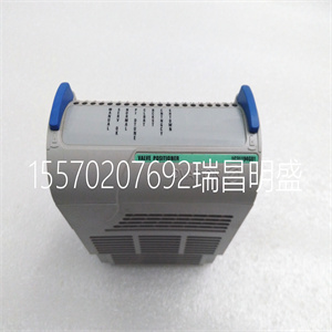


VE4003S2B2
3.2.1操作面板的拆卸和安装
1.拆卸
将中指插入顶部的孔中
操作面板,按下按扣并拉动
面板向外,如中所示。图3-4。
2.安装
将操作面板的底部边缘放置在
安装槽的挂钩,并向下压
16第3章安装和布线
EV2000系列通用变速驱动用户手册
用你的中指。然后按下面板
向内将其卡入位置,如图3-4所示。
3.
2.
1.
图3-4操作面板的拆卸和安装
其中:1和2:固定夹3:面板
3.2.2盖板的拆卸和安装
EV2000系列有两种盖子,塑料或
金属的。按照以下步骤删除和
装上盖子。
1.塑料盖的拆卸和安装
1) 删除:
① 卸下操作面板
② 拆下底部的两个螺钉
③ 将盖子底部提起5~10度,移动
向上至少10mm,直到卡箍脱离槽
在机柜上,然后拆下前面板。
2) 塑料盖的安装:
①将盖子倾斜5~10度;
②将顶部卡箍插入顶部的插槽中
驾驶
③安装盖子底部的螺钉;
④安装操作面板
图3-5塑料盖的拆卸和安装
注:
轻轻拉出或插入塑料盖,否则
安装夹可能损坏。
2.拆卸和安装金属的程序
掩蔽
1) 拆卸金属盖的步骤:
①拆下操作面板;
②拆下盖子上的所有螺钉;
③水平取出盖子。
2) 安装金属盖的步骤:
①用螺钉将盖子安装在框架上;
②安装操作面板。
图3-6拆卸和安装金属盖
第3章安装和布线17
EV2000系列通用变速驱动用户手册
3.3传动装置的接线
! 危险
·只能在驱动器交流后进行接线
电源断开,上的所有指示灯
操作面板关闭,至少等待5分钟
分钟然后,您可以移除面板。
·只有在确认
右下角的充电指示灯具有:
熄灭和主电路之间的电压
电源端子+和-低于DC36V。
·只有经过培训的和
授权人员。
·连接前仔细检查接线
紧急停止或安全电路。
·供电前检查驱动器的电压电平
电源,否则会造成人身伤害或设备损坏
可能会发生损坏。
! 注意
·检查变速驱动器是否额定
输入电压与交流电源一致
使用前的电压。
·对驱动器进行了介电强度测试
在工厂里,所以你不必再做了。
·参见第2章“连接的制动电阻”
或制动套件。
·禁止将交流电源电缆连接到:
驱动器的端子U、V和W。
·接地电缆应为铜电缆,带有:
截面积大于3.5mm2
,以及
接地电阻应小于10Ω。
·驱动器内部存在泄漏电流。总数
泄漏电流大于3.5mA,具体取决于
取决于使用条件。为了确保安全,两个
驱动器和电机应接地,并且
漏电保护器(RCD)应为:
安装。建议选择B型RCD
并将漏电流设置为300mA。
·驱动器应连接到交流电源
通过断路器或保险丝提供输入
过流保护或方便
断开交流电源以保持驱动器。
按照图3-7对驱动器进行布线
调试:
EV2000
U
五、
W
体育课
M
R
S
T
三相
自动控制
供给
QF
VRF
VCI
GND
前轮驱动
组件对象模型
.
.
.
.
.
.CCI修订版。
图3-7接线
3.3.1主端子的接线
1.驱动器和可选部件之间的连接
感应电动机
交流输入电抗器
交流输出电抗器
输入EMI滤波器
输出EMI滤波器
断路器或
保险丝
接触器
直流电抗器
PE U V W
EV2000
R S T
+
-
P1
制动装置
制动电阻
M
R
隔离开关
N
S
T
图3-8驱动器和可选部件之间的接线
1). 隔离开关应连接在
交流电源和驱动器,以确保
维修工程师。
2). 应连接断路器(QF)或保险丝
在交流电源和驱动器之间隔离故障
其他设备。选择见表3-1
断路器。
3) 当接触器用于控制交流时
电源,不要用它打开或关闭变量
服务提供商
VE4003S2B2
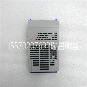
VE4003S2B2
3.2.1 Removing and Installation of Operation Panel
1. Disassembly
Put your middle finger into the hole on the top of
operation panel, press down the snapper and pull the
panel outward as shown in. Figure 3-4.
2. Installation
Place the bottom edge of the operation panel at the
hooks of the mounting groove and press down the
16 Chapter 3 Installation and Wiring
EV2000 Series Universal Variable Speed Drive User Manual
snapper with your middle finger. Then press the panel
inward to snap it in position as shown in Figure 3-4.
3
2
1
Fig. 3-4 Removing and Mounting of Operation Panel
Where: 1&2: holding clamp 3:panel
3.2.2 Removing and Mounting of Cover
EV2000 series have two kinds of cover, plastic or
metallic one. Follow the steps below to remove and
mount the cover.
1. Removing and mounting of plastic covers
1) Removing:
① Remove the operation panel
② Remove two screws at bottom
③ Lift the bottom of cover up to 5~10 degrees, move it
upward at least 10mm until the clamp are out of the slot
on the cabinet, then remove the front panel.
2) Mounting of plastic cover:
①Tilt the cover 5~10 degree;
②Insert the top clamp into the slot at the top of the
drive;
③Mount the screws at the bottom part of the cover;
④Install the operation panel
Fig. 3-5 Removing and installation of plastic cover
Note:
Pull out or insert the plastic cover gently, otherwise the
mounting clamp may be damaged.
2. Procedures of removing and mounting the metal
cover
1) Procedures of removing the metal cover:
①Remove the operational panel;
②Remove all the screws on the cover;
③Take out the cover horizontally.
2) Procedures of installing the metal cover:
①Mount the cover on the frame by screws;
②Install the operation panel.
Fig. 3-6 Removing and mounting metal cover
Chapter 3 Installation and Wiring 17
EV2000 Series Universal Variable Speed Drive User Manual
3.3 Wire Connections of Drive
! Danger
·Wiring can only be done after the drive’s AC
power is disconnected, all the LEDs on the
operation panel are off and waiting for at least 5
minutes. Then, you can remove the panel.
·Wiring job can only be done after confirming the
charge indicator on the right bottom has
extinguished and the voltage between main circuit
power terminals + and - is below DC36V.
·Wire connections can only be done by trained and
authorized personnel.
·Check the wiring carefully before connecting
emergency stopping or safety circuits.
·Check the drive’s voltage level before supplying
power to it, otherwise human injuries or equipment
damage may happen.
! Attention
·Check whether the Variable Speed Drive’s rated
input voltage is in compliant with the AC supply
voltage before using.
·Dielectric strength test of the drive has been done
in factory, so you need not do it again.
·Refer to chapter 2 on connected braking resistor
or braking kit.
·It is prohibited to connect the AC supply cables to
the drive’s terminals U, V and W.
·Grounding cables should be copper cables with
section area bigger than 3.5mm2
, and the
grounding resistance should be less than 10Ω.
·There is leakage current inside the drive. The total
leakage current is greater than 3.5mA, depending
on the usage conditions. To ensure safety, both the
drive and the motor should be grounded, and a
leakage current protector (RCD) should be
installed. It is recommended to choose B type RCD
and set the leakage current at 300mA.
·The drive should be connected to the AC supply
via a circuit breaker or fuse to provide input
over-current protection or convenience for
disconnecting the AC supply to maintain the drive.
Wire the drive according to Fig. 3-7 during
commissioning :
EV2000
U
V
W
PE
M
R
S
T
3-phase
AC
supply
QF
VRF
VCI
GND
FWD
COM
.
.
.
.
.
. CCI REV .
Fig. 3-7 Wiring
3.3.1 Wire Connections of Main Terminals
1. Connection between drive and optional parts
IM
AC input reactor
AC output reactor
Input EMI filter
Output EMI filter
Circuit breaker or
fuse
Contactor
DC reactor
PE U V W
EV2000
R S T
+
-
P1
Braking unit
Braking resistor
M
R
Isolator switch
N
S
T
Fig. 3-8 Wire connection between the drive and optional parts
1). Isolation switch should be connected between the
AC supply and the drive to ensure the safety of the
maintenance engineer.
2). Circuit breaker (QF) or fuse should be connected
between the AC supply and the drive to isolate the fault
of other equipment. Refer to Table 3-1 for the selection
of circuit breaker.
3) When a contactor is used for controlling the AC
supply, don’t use it to switch on or off the Variable
Sp
Copyright ©2019-2022 瑞昌明盛自动化设备有限公司 版权所有 赣ICP备2021006016号


