


5X00121G01
设计
重量标准版本:…kg,取决于设备
宽版:…kg,取决于设备
HMI安装类型:半暗装在低压门上
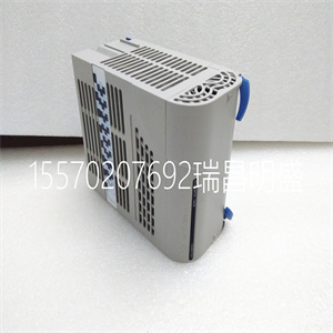
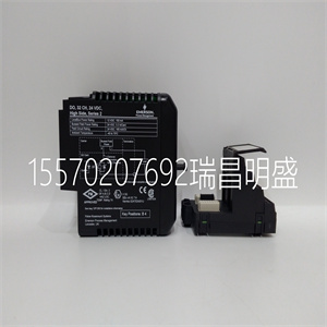
中央单元:在低压室内
尺寸185 x 244.8 x 261.5 mm(宽x高x深)标准版
229 x 244.8 x 261.5毫米宽版本
面板切口206 x 121 mm(宽x高)
4.2.1设置区域和所需环境条件
请注意以下关于设置区域的信息:
为访问提供足够的空间。连接必须易于接近。
出于以下原因,必须易于接近低压室中的中央单元:
为了更换该单元,
为了扩展单元,
更换特定的电子设备板,以及
如有必要,更换特定模块。
由于该单元对不允许的恶劣环境条件敏感,
请遵守以下规定:
设置区域必须无过度空气污染(灰尘、腐蚀性物质…)。
机组周围的自然空气循环必须是自由的。
设置区域必须保持规定的环境条件
REF 542plus开关间保护和控制单元
手册3部分:安装和调试
1VTA10004 en DMS,2001-10-04参考542 Plus:安装和调试15/80
4.2.2低压配电盘安装
图4:安装在气体绝缘开关设备(GIS)中的REF542plus
图5:安装在空气绝缘开关设备(AIS)中的REF542plus
REF 542plus开关间保护和控制单元
手册3部分:安装和调试
1VTA10004 en DMS,2001-10-04参考542 Plus:安装和调试16/80
图6:低压室中中央单元的安装示例
门上的HMI
4.2.3连接图
连接板
图1:REF542plus连接器板,用于宽壳混合模拟输入版本
REF 542plus开关间保护和控制单元
手册3部分:安装和调试
1VTA10004 en DMS,2001-10-04参考542 Plus:安装和调试17/80
图2:REF542plus连接器板,用于短路混合模拟输入版本
图3:REF542带变压器或传感器的模拟输入用插头连接器板
REF 542plus开关间保护和控制单元
手册3部分:安装和调试
1VTA10004 en DMS,2001-10-04参考542 Plus:安装和调试18/80
表2:中央单元上的连接器
连接器说明:连接器插头类型
X10电源辅助电压,3引脚Weidmueller,母布拉特3BSNOR
+固定集Slabb2rSet
DIN 416121个BIO Harting 09 06 000 9474的X20二进制输入
DIN 416121个BIO Harting 09 06 000 9474的X21二进制输出
X30二个BIO Harting 09 06 000 9474的二进制输入,DIN 41612
X31二生物哈廷09 06 000 9474的二进制输出,DIN 41612
DIN 41612三生物哈廷09 06 000 9474的X40二进制输入
X41三代生物哈廷09 06 000 9474的二进制输出,DIN 41612
X50模拟输出Harting 09 06 000 9474,DIN 41612
X70以太网接口(完整版)尚不可用
X71 CAN接口(完整版本)尚不可用
X72 RS232接口9针D-sub公接头
X73 RS485接口9针D-sub公接头
X74 IRIG-B接口(完整版)尚不可用
X75快速I/O输入(完整版)尚不可用
X76快速I/O输出(完整版)尚不可用
X77快速I/O输入(完整版)尚不可用
X80模拟输入(来自CT和/或VT)连接器套件强制c/w 24触点
-短版本代码350.040.902
-长版本代码350.040.903
用手动工具压接任何单个触点
编号:350.048.011
X81..88模拟输入(传感器通道1..8)BNC双凸轮CPE 23.717.140-0333
表3:用于SPABUS连接的中央单元上的连接器,电气
5X00121G01

5X00121G01
Design
Weight Standard version: … kg depending on equipment
Wide version: … kg depending on equipment
Installation type HMI: semiflush on the LV door
Central unit: in the LV compartment
Dimensions 185 x 244.8 x 261.5 mm (W x H x D) Standard version
229 x 244.8 x 261.5 mm (W x H x D) Wide version
Panel cutout 206 x 121 mm (W x H)
4.2.1 Set-up Area and Required Environmental Conditions
Please note the following information regarding the set-up area:
Allow sufficient space for access to the. The connections must be easily accessible.
Access to the Central Unit in the LV compartment must be easy for the following reasons:
to replace the unit,
to expand the unit,
to replace specific electronic equipment boards and
to replace specific modules if necessary.
Because the unit is sensitive to non-permitted severe environmental conditions,
please observe the following:
The set-up area must be free of excessive air contamination (dust, aggressive substances…).
The natural air circulation around the unit must be free.
The set-up area must maintain the specified environmental conditions
REF 542plus switchbay protection and control unit
Manual Part 3: Installation and Commissioning
1VTA100004-en DMS,2001-10-04 REF542plus: Installation and Commissioning 15 / 80
4.2.2 Installation in LV panels
Figure 4: REF542plus installed in gas-insulated switchgears (GIS)
Figure 5: REF542plus installed in air-insulated switchgears (AIS)
REF 542plus switchbay protection and control unit
Manual Part 3: Installation and Commissioning
1VTA100004-en DMS,2001-10-04 REF542plus: Installation and Commissioning 16 / 80
Figure 6: Example of mounting of the Central Unit in the LV compartment and the
HMI on the door
4.2.3 Connection diagrams
Connector Plate
Figure 1: REF542plus connector plate for the wide case mixed analog input version
REF 542plus switchbay protection and control unit
Manual Part 3: Installation and Commissioning
1VTA100004-en DMS,2001-10-04 REF542plus: Installation and Commissioning 17 / 80
Figure 2: REF542plus connector plate for the short case mixed analog input version
Figure 3: REF542plus connector plate for analog input with transformers or with sensors
REF 542plus switchbay protection and control unit
Manual Part 3: Installation and Commissioning
1VTA100004-en DMS,2001-10-04 REF542plus: Installation and Commissioning 18 / 80
Table 2: Connectors on Central Unit
Connector Descriptions Type of connector plug
X10 Auxiliary voltage for power supply 3 pin Weidmueller female BLAT3BSNOR
+ fixing set SLABB2RORSET
X20 Binary Inputs of the 1st BIO Harting 09 06 000 9474, DIN 41612
X21 Binary outputs of the 1st BIO Harting 09 06 000 9474, DIN 41612
X30 Binary Inputs of the 2nd BIO Harting 09 06 000 9474, DIN 41612
X31 Binary outputs of the 2nd BIO Harting 09 06 000 9474, DIN 41612
X40 Binary Inputs of the 3rd BIO Harting 09 06 000 9474, DIN 41612
X41 Binary outputs of the 3rd BIO Harting 09 06 000 9474, DIN 41612
X50 Analog output Harting 09 06 000 9474, DIN 41612
X70 Ethernet interface (full version) Not available yet
X71 CAN interface (full version) Not available yet
X72 RS232 interface 9 pin D-sub connector male
X73 RS485 interface 9 pin D-sub connector male
X74 IRIG-B interface (full version) Not available yet
X75 Fast I/O inputs (full version) Not available yet
X76 Fast I/O outputs (full version) Not available yet
X77 Fast I/O inputs (full version) Not available yet
X80 Analog inputs (from CT and/or VT) Connector kit Compel c/w 24 contacts
- Short version code 350.040.902
- Long version code 350.040.903
Crimp any single contact with hand tool
No 350.048.011
X81..88 Analog input (sensor channel 1..8) BNC Twin Cam CPE 23.717.140-0333
Table 3: Connectors on Central Unit for SPABUS connection, electric
Copyright ©2019-2022 瑞昌明盛自动化设备有限公司 版权所有 赣ICP备2021006016号


