


140XCA71706
c和电磁
领域
工频磁场
现场(IEC 61000-4-8,EN
61000-4-8)
脉冲磁场(IEC
61000-4-9,EN 61000-3-9)
阻尼振荡磁
0.1MHz和1MHz磁场(IEC
61000-4-10,EN 61000-3-10)
辐射射频
电磁场,80MHz
至1GHz(IEC 61000-4-3)
辐射射频
磁场,900±5 MHz(环境
50204)
射频公用
模式、幅度调制,
0.15 MHz至80 MHz(IEC
61000-4-6)
连续:30臂/米
短时:300臂/米
峰值:300 A/m
峰值:30 A/m
未调制RMS:10 V/m
调幅:80%调幅(1 kHz)
未调制RMS:10 V/m
脉冲调制:占空比50%,重复周期200 Hz
未调制RMS:10 V
调幅:80%调幅(1 kHz)
源阻抗:150!
射频辐射发射试验
场,30 MHz至1000 MHz
(EN 55011)
甲级
安装占用标准模块安装单元中的单个插槽。
环境
环境温度
相对湿度
海拔高度
空气质量
0°至70°C(32°至158°F)
55°C(131°F)下的5%至95%(非冷凝)
70°C(158°F)条件下的5%至45%(非冷凝)
污染程度:1
海平面上升至3公里(1.86英里)
非腐蚀性
装运重量1.146千克(2.5磅)
容器尺寸27.94厘米x 35.56厘米x 5.54厘米(11英寸x 14英寸x 3英寸)
表1-4.规范(续)
公关声明
EMC96指令89/336/EEC
低压指令73/23/
欧共体
本产品安装在Symphony机柜中时,符合
符合CE标志的以下指令/标准。
EN50082-2通用抗扰度标准-2部分:工业
环境
EN50081-2通用排放标准-2部分:工业
环境
EN61010-1电气设备的安全要求
测量、控制和实验室使用.1部分:总则
要求
所获证书
CSA(待定)
工厂互助(FM)
(待定)
经认证可作为普通过程控制设备使用
(非危险)位置。
批准为I类使用的非易燃设备;分开
2.A、B、C、D组;危险地点。
注:
1.对大额定值表示超出可能对设备造成损坏且无法保证设备运行的极限值。
规格如有更改,恕不另行通知
表1-4.规范(续)
特性/价值
WBPEEUI240774A0 2-1
说明和操作2节
介绍
本节解释了输入、控制逻辑、通信和通信,
以及IMASI23模块的连接。ASI模块
将16个模拟输入连接到和声控制器。和谐控制器通过
I/O扩展器总线(图1-1)。总线上的每个I/O模块都有一个
由其地址双列直插开关(S1)设置的地址。
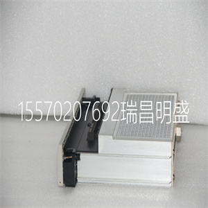
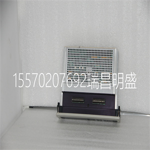
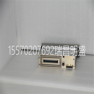
模块描述
ASI模块由单个印刷电路板组成,该印刷电路板:
占用模块安装单元(MMU)中的一个插槽。模块前面板上的两个固定闩锁将其固定到模块上
安装单元。
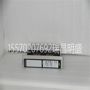
ASI模块有三个外部卡边缘连接器
信号和电源:P1、P2和P3。P1连接到电源
电压。P2将模块连接到I/O扩展器总线,
它通过该总线与控制器通信。连接器P3
将终端电缆的输入端插入
终端单元(TU)。现场接线的接线端子为:
在终端单元上。
模块上的单个双列直插开关设置其地址或选择
船上测试。跳线配置模拟输入信号的类型。
功能操作
ASI模块是一个带板载的智能模块
微控制器和存储器。它通过以下接口连接到控制器:
I/O扩展器总线。板载微控制器允许
ASI模块执行输入通道处理。这
允许控制器执行其他任务。输入处理任务
包括误差补偿、调整和转换为
工程单位。
2-2 WBPEEUI240774A0
功能操作
每个通道提供
140XCA71706
140XCA71706
c and electromagnetic
fields
Power frequency magnetic
field (IEC 61000-4-8, EN
61000-4-8)
Pulse magnetic field (IEC
61000-4-9, EN 61000-4-9)
Damped oscillatory magnetic
field, 0.1 MHz and 1 MHz (IEC
61000-4-10, EN 61000-4-10)
Radiated radio-frequency
electromagnetic field, 80 MHz
to 1GHz (IEC 61000-4-3)
Radiated radio-frequency
field, 900 ±5 MHz (ENV
50204)
Radio-frequency common
mode, amplitude modulated,
0.15 MHz to 80 MHz (IEC
61000-4-6)
Continuous: 30 ARMS/m
Short duration: 300 ARMS/m
Peak value: 300 A/m
Peak value: 30 A/m
Unmodulated RMS: 10 V/m
Amplitude modulated: 80% AM (1 kHz)
Unmodulated RMS: 10 V/m
Pulse modulated: Duty cycle 50%, Rep. cycle 200 Hz
Unmodulated RMS: 10 V
Amplitude modulated: 80% AM (1 kHz)
Source impedance: 150 !
Emission test RF radiated
fields, 30 MHz to 1000 MHz
(EN 55011)
Class A
Mounting Occupies a single slot in a standard module mounting unit.
Environment
Ambient temperature
Relative humidity
Altitude
Air quality
0° to 70° C (32° to 158° F)
5% to 95% up to 55° C (131° F) (noncondensing)
5% to 45% at 70° C (158° F) (noncondensing)
Pollution degree: 1
Sea level to 3 km (1.86 miles)
Noncorrosive
Shipping weight 1.146 kg (2.5 lb)
Container size 27.94 cm x 35.56 cm x 5.54 cm (11 in. x 14 in. x 3 in.)
Table 1-4. Specifications (continued)
Pr declaration
EMC96 Directive 89/336/EEC
Low Voltage Directive 73/23/
EEC
This product, when installed in a Symphony cabinet, complies
with the following Directives/Standards for CE marking.
EN50082-2 Generic Immunity Standard - Part 2: Industrial
Environment
EN50081-2 Generic Emission Standard - Part 2: Industrial
Environment
EN61010-1 Safety Requirements for Electrical Equipment for
Measurement, Control and Laboratory Use - Part 1: General
Requirements
Certifications
CSA (pending)
Factory Mutual (FM)
(pending)
Certified for use as process control equipment in an ordinary
(nonhazardous) location.
Approved as nonincendive equipment for use in Class I; Division
2; Groups A, B, C, D; hazardous location.
NOTE:
1. Absolute maximum ratings indicate limits beyond which damage to the device may occur and device operation is not guaranteed.
SPECIFICATIONS ARE SUBJECT TO CHANGE WITHOUT NOTICE
Table 1-4. Specifications (continued)
Property Characteristic/Value
WBPEEUI240774A0 2 - 1
Description and Operation Section 2
Introduction
This section explains the inputs, control logic, communication,
and connections for the IMASI23 module. The ASI module
interfaces 16 analog inputs to a Harmony controller. The Harmony controller communicates with its I/O modules over the
I/O expander bus (Fig. 1-1). Each I/O module on the bus has a
unique address set by its address dipswitch (S1).
Module Description
The ASI module consists of a single printed circuit board that
occupies one slot in a module mounting unit (MMU). Two captive latches on the module front panel secure it to the module
mounting unit.
The ASI module has three card edge connectors for external
signals and power: P1, P2 and P3. P1 connects to the supply
voltages. P2 connects the module to the I/O expander bus,
over which it communicates with the controller. Connector P3
carries the inputs from the termination cable plugged into the
termination unit (TU). The terminal blocks for field wiring are
on the termination unit.
A single dipswitch on the module sets its address or selects
onboard tests. Jumpers configure the type of analog input signals.
Functional Operation
The ASI module is an intelligent module with an onboard
microcontroller and memory. It interfaces to a controller over
the I/O expander bus. An onboard microcontroller allows the
ASI module to perform the input channel processing. This
allows the controller to do other tasks. Input processing tasks
include error compensation, adjustments, and conversion to
engineering units.
2 - 2 WBPEEUI240774A0
Functional Operation
Each channel provides
Copyright ©2019-2022 瑞昌明盛自动化设备有限公司 版权所有 赣ICP备2021006016号


