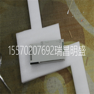


140XCP40100
每个A/D转换器连续采样输入信号
而不需要开始转换命令。A/D输出
寄存器以内部过滤器确定的速率更新
并且可以随时准备好。ASI模块扫描所有A/D
转换器输出寄存器的速率约为180毫秒
包括校准和开路测试。
除输入通道外,在正常输入扫描期间读取内置冷结参考。
自动调整和校正
WBPEEUI240774A0 2-7
点值计算
ASI模块为每个模块维护一组调整值
输入通道。这些值可校正偏移和增益误差
在输入通道中。原始模数转换器计数
使用校准数据将值转换为实际输入信号值。
对于热电偶输入,对冷态进行调整
热电偶的结温。另外,
然后应用用户指定的调整,如果已经
用FC 217定义。终校正的输入读数为
使用热电偶或转换为工程单位
RTD转换表,或工程单位零点和量程
为输入指定的值。
以下各节描述了各种类型的输入值
调整。
输入校准
每个输入通道在工厂进行校准。在校准过程中,识别任何偏移和增益误差
并计算所需的校正系数,并将其存储在
模拟输入模块的非易失性存储器。
当输入通道被扫描到
纠正读数。校准调整应用于:
有源通道和冷结参考输入。
冷端补偿
热电偶输入通道针对冷端进行调整
温度冷接点参考可以是
I/O模块终端上的内置参考
单位或源自任何其他功能代码块的值
输出系统中的任何位置。冷接点参考
假设由控制器提供的温度为摄氏度
ASI模块将此值转换为毫伏,并将其添加到
来自模数转换器的值。
热电偶通道确定为冷接点参考
输入(FC 216,规格S4)使用内置冷接点
终端装置的冷端补偿参考。
2-8 WBPEEUI240774A0
自动调整和校正
用户增益和偏移调整
用户指定的线性调整可应用于输入
转换为工程单位之前的信号。这个增益和
偏移量应用于所有补偿后获得的值
并且执行校正操作。
用户偏移和增益补偿用于用户校正的输入信号。例如,如果0至10 VDC模拟输入为0.1 VDC
过高时,ASI模块可以通过为该通道和输入类型添加-0.1的偏移值来补偿该偏移。
对于高电平输入,用户增益值乘以伏特,乘以
低电平输入和热电偶输入的毫伏,以及
电阻式温度检测器输入的欧姆。默认用户增益值为1。
用户偏移被添加到输入信号。偏移单位被指定为高电平输入的伏特、低电平输入的毫伏,
电阻式温度检测器输入为欧姆。默认用户偏移量为
零可以为指定单独的用户增益和偏移值
每个输入通道和每个输入类型。可以使用FC 217设置和重置用户增益和偏移值,
用户增益和偏移值保留在非易失性存储器中,以及
当模块电源中断时不会丢失。有关更多信息,请参阅中的FC 217
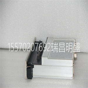
140XCP40100

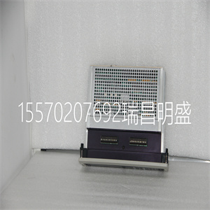
140XCP40100
Each A/D converter samples the input signal continuously
without need for a start convert command. The A/D output
register is updated at a rate determined by the internal filter
and can be ready at any time. The ASI module scans all A/D
converter output registers at a rate of about 180 milliseconds
including calibration and open circuit tests.
In addition to the input channels, the built-in cold junction reference is read during normal input scanning.
Automatic Adjustments and Corrections
WBPEEUI240774A0 2 - 7
Point Value Calculation
The ASI module maintains a set of adjustment values for each
input channel. These values correct for offset and gain errors
in the input channel. The raw analog-to-digital converter count
value is converted to an actual input signal value using the calibration data.
For thermocouple inputs, an adjustment is made for the cold
junction temperature of the thermocouple. An additional,
user-specified adjustment is then applied, if one has been
defined with FC 217. The final corrected input reading is then
converted to engineering units using either thermocouple or
RTD conversion tables, or the engineering unit zero and span
values specified for the input.
The following sections describe the various types of input value
adjustments.
Input Calibration
Each input channel is calibrated at the factory. During the calibration procedure, any offset and gain errors are identified
and required correction factors are calculated and stored in the
analog input module's nonvolatile memory.
These factors are used when the input channel is scanned to
correct the reading. A calibration adjustment is applied to
active channels and the cold junction reference input.
Cold Junction Compensation
Thermocouple input channels are adjusted for cold junction
temperature. The cold junction reference can either be the
built-in reference available on the I/O module's termination
unit or a value originating from any other function code block
output anywhere in the system. The cold junction reference
supplied by the controller is assumed to be in degrees C. The
ASI module converts this value to millivolts and adds it to the
value from the analog-to-digital converter.
Thermocouple channels identified to be cold junction reference
inputs (FC 216, specification S4) use the built-in cold junction
reference on the termination unit for their cold junction compensation.
2 - 8 WBPEEUI240774A0
Automatic Adjustments and Corrections
User Gain and Offset Adjustment
A user-specified linear adjustment can be applied to the input
signal before it is converted to engineering units. This gain and
offset is applied to the value obtained after all compensation
and correction operations are performed.
User offset and gain compensates input signals for user corrections. For example, if a 0 to 10 VDC analog input is 0.1 VDC
too high, the ASI module can compensate for this offset by adding an offset value of -0.1 for this channel and input type.
User gain value is multiplied by volts for high level inputs, by
millivolts for low level inputs and thermocouple inputs, and by
ohms for RTD inputs. The default user gain is a value of one.
User offset is added to the input signal. Units of offset are specified as volts for high level inputs, millivolts for low level inputs,
and ohms for RTD inputs. The default user offset is a value of
zero. Separate user gain and offset values can be specified for
each input channel and each input type. The user gain and offset values can be set and reset using FC 217. Once defined,
user gain and offset values remain in nonvolatile memory and
are not lost when module power is interrupted. For more information refer to FC 217 in th
Copyright ©2019-2022 瑞昌明盛自动化设备有限公司 版权所有 赣ICP备2021006016号


