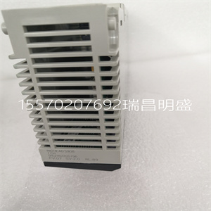


140DAI45300
使用寿命1200毫安时
保质期:10年,每年容量损失0.5%
CPU模块
840使用100 00 2002年9月167
*该信息可以是离散或寄存器I/O的混合。对于寄存器的每个字
配置I/O时,必须从可用的总I/O字中减去一个字。
这同样适用于每个8位或16位离散I/O配置块——
寄存器I/O的一个字必须从可用总数中减去。
**需要使用两个140NOM21x00选件模块。
断电时的电池负载电流
典型7µA
大210µA
表达
Modbus(RS-232)2串行端口(9针D壳)
Modbus Plus(RS-485)1个网络端口(9针D壳)
全体的
诊断加电运行时
RAM RAM
RAM地址RAM地址
执行校验和执行校验和
用户逻辑检查用户逻辑检查
加工机
所需母线电流:1.8 A
功耗9W
TOD时钟+/-8.0秒/天0…60°C
工作温度0…60°C
规格
CPU模块
168 840使用100 00 2002年9月
LED指示灯
和说明
下图显示了LED指示灯。
下表显示了LED说明。
开启时LED颜色指示
绿色就绪-CPU已通过通电诊断。
绿色运行CPU已启动并正在解决逻辑。
Bat低红色-电池需要更换或不存在。
Modbus绿色通信在Modbus端口1或2上激活。
Modbus+绿色通信在Modbus+端口上激活。
错误红色表示Modbus Plus端口上的通信错误。
Mem Prt琥珀色内存受写保护(内存保护开关接通)。
Bat1低
准备好的
跑
Modbus
Modbus+错误A
Mem Prt
CPU模块
840使用100 00 2002年9月169
LED错误代码下表显示了140CPU43412的运行LED错误代码。
LED错误代码
闪烁次数代码错误
连续0000请求内核模式
2.调整大小时出现80B ram错误
80C运行输出激活失败
82E MB命令处理程序堆栈错误
收到3769笔巴士津贴
72A不是cpu上的主asic
72B主配置写入错误
72C量子总线DPM写入失败
72F plc asic环回测试
730 plc asic BAD_DATA
CPU模块
170 840使用100 00 2002年9月
4 604 UPI超时错误
605错误UPI响应操作码
606 UPI总线诊断错误
607 modbus cmd缓冲区溢出
608 modbus cmd长度为零
609 modbus中止命令错误
614 mbp总线接口错误
615错误的mbp响应操作码
616等待mbp超时
617 mbp不同步
618 mbp无效路径
619第0页未对齐段落
61E外部uart硬件不良
61F外部uart中断错误
620接收通信状态不良
621传输通信状态不良
622不良通信状态trn_asc
623错误通信状态trn_rtu
624错误通信状态rcv_rtu
625不良通信状态rcv_asc
626不良modbus状态tmr0_evt
627不良modbus状态trn int
628不良modbus状态rcv int
631错误中断
5 503 ram地址测试错误
52D P.O.S.T错误的MPU错误
6 402 ram数据测试错误
7300 EXEC未加载
301执行校验和
8 8001内核prom校验和错误
8002闪存编程/擦除错误
8003意外高管回归
LED错误代码
闪烁次数代码错误
CPU模块
840使用100 00 2002年9月171
前面板
开关
两个、三个位置的滑动开关位于CPU的前部。左派
当处于顶部位置且无内存时,开关用于内存保护
中间和底部位置的保护。上的三位滑动开关
右侧用于选择Modbus(RS-232)端口的通信参数设置。
下图显示了140CPU43412可用的三个选项
单元
将滑动开关设置到顶部位置将ASCII功能分配给端口;这个
以下通信参数已设置且无法更改。
将滑动开关设置到中间位置将分配远程终端单元(RTU)
端口的功能;以下通信参数已设置,不能
改变。
注:当前面板开关处于以下状态时,CPU硬件默认为桥接模式
设置为RTU或ASCII模式。连接控制器时,面板设备连接
到CPU,Modbus端口可以与控制器通信
连接,以及登录Modbus Plus网络上的任何节点。
140DAI45300

140DAI45300
ervice Life 1200 mAh
Shelf Life 10 years with 0.5% loss of capacity per year
CPU Modules
840 USE 100 00 September 2002 167
*This information can be a mix of Discrete or Register I/Os. For each word of register
I/O configured, one word of I/O words must be subtracted from the total available.
The same holds true for each block of 8 bits or 16 bits of Discrete I/O configured –
one word of Register I/O must be subtracted from the total available.
**Requires the use of two 140NOM21x00 Option Modules.
Battery Load Current at Power-off
Typical 7 µA
Maximum 210 µA
Communication
Modbus (RS-232) 2 serial port (9-pin D-shell)
Modbus Plus (RS-485) 1 network port (9-pin D-shell)
General
Diagnostics Power Up Runtime
RAM RAM
RAM Address RAM Address
Executive Checksum Executive Checksum
User Logic Check User Logic Check
Processor
Bus Current Required 1.8 A
Power Dissipation 9W
TOD Clock +/- 8.0 seconds/day 0 ... 60° C
Operating Temperature 0 ... 60° C
Specifications
CPU Modules
168 840 USE 100 00 September 2002
LED Indicators
and Descriptions
The following figure shows the LED indicators.
The following table shows the LED descriptions.
LEDS Color Indication when On
Ready Green The CPU has passed power-up diagnostics.
Run Green The CPU has been started and is solving logic.
Bat Low Red The battery needs replacing or is not present.
Modbus Green Communications are active on the Modbus port 1 or 2.
Modbus + Green Communications are active on the Modbus Plus port.
Error A Red Indicates communications error on the Modbus Plus port.
Mem Prt Amber Memory is write-protected (the memory protect switch is on).
Bat1 Low
Ready
Run
Modbus
Modbus + Error A
Mem Prt
CPU Modules
840 USE 100 00 September 2002 169
LED Error Codes The following table shows the run LED error codes for the 140CPU43412.
LED Error Codes
Number of Blinks Code Error
Continuous 0000 requested kernel mode
2 80B ram error during sizing
80C run output active failed
82E MB command handler stack error
3 769 bus grant received
72A not master asic on cpu
72B master config write bad
72C quantum bus DPM write failure
72F plc asic loopback test
730 plc asic BAD_DATA
CPU Modules
170 840 USE 100 00 September 2002
4 604 UPI timeout error
605 bad UPI response opcode
606 UPI bus diagnostic error
607 modbus cmd-buffer overflow
608 modbus cmd-length is zero
609 modbus abort command error
614 mbp bus interface error
615 bad mbp response opcode
616 timeout waiting for mbp
617 mbp out of synchronization
618 mbp invalid path
619 page 0 not paragraph aligned
61E bad external uart hardware
61F bad external uart interrupt
620 bad receive comm state
621 bad transmit comm state
622 bad comm state trn_asc
623 bad comm state trn_rtu
624 bad comm state rcv_rtu
625 bad comm state rcv_asc
626 bad modbus state tmr0_evt
627 bad modbus state trn-int
628 bad modbus state rcv-int
631 bad interrupt
5 503 ram address test error
52D P.O.S.T BAD MPU ERROR
6 402 ram data test error
7 300 EXEC not loaded
301 EXEC Checksum
8 8001 Kernal prom checksum error
8002 flash prog / erase error
8003 unexpected executive return
LED Error Codes
Number of Blinks Code Error
CPU Modules
840 USE 100 00 September 2002 171
Front Panel
Switches
Two, three-position slide switches are located on the front of the CPU. The left
switch is used for memory protection when in the top position and no memory
protection in the middle and bottom positions. The three-position slide switch on the
right is used to select the comm parameter settings for the Modbus (RS-232) ports.
The following figure shows the three options that are available for the 140CPU43412
module.
Setting the slide switch to the top position assigns ASCII functionality to the port; the
following comm parameters are set and cannot be changed.
Setting the slide switch to the middle position assigns remote terminal unit (RTU)
functionality to the port; the following comm parameters are set and cannot be
changed.
Note: The CPU hardware defaults to bridge mode when the front panel switch is
set to RTU or ASCII mode. When networking controllers, a panel device connected
to the CPU Modbus port can communicate with the controller to which it is
connected, as well as log into any nodes on the Modbus Plus network.
Copyright ©2019-2022 瑞昌明盛自动化设备有限公司 版权所有 赣ICP备2021006016号


