


MSK075C-0300-NN-M1-UG0-NNNN
模块。
MVME162提供了对大多数选项的软件控制:通过在
控制寄存器在系统中安装MVME162后,您可以修改
配置(MVME162寄存器在4章和/或
MVME162嵌入式控制器程序员参考指南,如中所列
1章中的相关文件。)
但是,有些选项不是软件可编程的。这些选择包括:
通过手动安装或拆除接头、跳线或接口进行控制
模块。
硬件准备和安装
2-2 MVME162嵌入式控制器用户手册
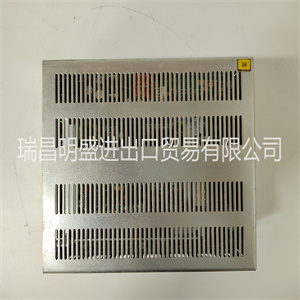
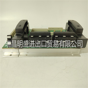
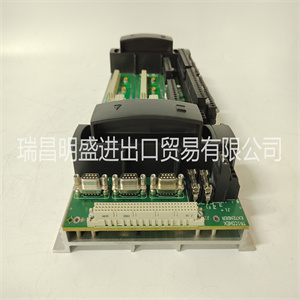
2图2-1说明了开关、跳线头和电缆的位置,
MVME162上的连接器和LED指示灯。可手动配置
项目包括:
❏ 串行端口B配置的SIM卡选择(J10)
❏ 系统控制器选择(J1)
❏ 串行端口1/控制台的同步时钟选择(J11)
❏ 串行端口2的同步时钟选择(J12)
❏ SRAM备用电源选择(J20)
❏ EPROM尺寸选择(J21)
❏ 通用可读寄存器配置(J22)
MVME162已经过工厂测试,并随配置一起出厂
如以下各节所述。MVME162所需的工厂安装调试监视器MVME162Bug(162Bug)与这些工厂一起运行
设置。
SIM卡选择
MVME162的Z85230串行通信控制器的端口B为:
可通过安装在连接器上的串行接口模块(SIM)进行配置
MVME162板上的J10。四个串行接口模块可用:
❏ EIA-232-D(DCE和DTE)
❏ EIA-530(DCE和DTE)
通过安装适当的串行接口模块,您可以将端口B从EIA-232-D更改为EIA-530接口(或反之亦然)。端口B被路由
(通过J10上的SIM卡)连接到标记为串行的25针DB25前面板连接器
端口2。
有关MVME162上SIM连接器J10的位置,请参阅图2-1。
图2-2说明了串行接口模块的二次侧(底部),
显示了J1接头,该接头插入到上的SIM接头J10
MVME162.图2-3(3-6页)、图2-4(3至4页)和图2-5
说明端口B的可用配置。
有关串行接口模块的零件号,请参阅表2-1
零件号通常打印在SIMs的主面(顶部),但
在某些版本中,可以在次级侧找到。
如果您需要将现有串行接口模块替换为另一个的SIM卡
类型,请转到下面的删除现有SIM卡。如果主板上没有SIM卡,
跳到安装新SIM卡。
硬件准备
MVME162/D2 2-3
2.
图2-1 MVME162开关、插头、连接器、保险丝和LED位置S1 S2 J15 13 1 25 14 P1
3.
1.
C1
地下一层
A1
C32
B32
A32
40
cb232 9212
MVME
162-XX
初级侧
P2
C32
B32
A32
C1
地下一层
A1
J9 13 1 25 14
DS4
50
49
2.
1 J5
50
49
2.
1 J6
20
19 J4
DS3
DS2
DS1
2.
1.
2.
1.
J1
49
50
24
25 1
2.
26
27
J3
49
一层楼
地上二层
39 1
2 P3
J8
J2 J7
39
40
1.
24页
J14 J19
J13 J18
1.
2.4 J12
1.
2.4 J11 39
40
1.
2 J10
J21和J20
5 6
1 2
15 1
16
J22
串行端口2串行端口1/控制台故障状态
运行SCON
局域网保险丝
SCSI VME
中止
复位
50
49
2.
1 J16
50
49
2.
1 J17
49
50
24
25 1
2.
26
27 49
50
24
25 1
2.
26
27 49
50
24
25 1
2.
26
27
49
50
24
25 1
2.
26
27 49
50
24
25 1
2.
26
27 49
50
24
25 1
2.
26
27 49
50
24
25 1
2.
26
27
2.
硬件准备和安装
2-4 MVME162嵌入式控制器用户手册
2.
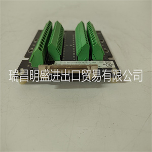
图2-2.连接器侧串行接口模块
删除现有SIM卡
1.每个串行接口模块由两个4-40 x 3
/16“菲利普斯头
在相反的角上拧上螺钉。拆下两个螺钉并将其存放在
供以后使用的安全场所。
2.抓住SIM卡的两侧,轻轻向上提起。
注意:避免仅从一侧提起SIM卡,因为连接器可能
SIM卡或主板损坏。
3.将SIM卡放在静态安全容器中,以备再次使用。
表2-1.串行接口模块零件号
环境影响评估
标准配置零件号型号
数字
EIA-232-D DTE 01-W3846B SIM05
DCE 01-W3865B SIM06
EIA-530 DTE 01-W3868B SIM07
DCE 01-W3867B SIM08
10922.00 9403 (2-2)
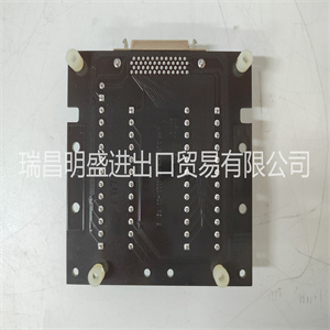
次级侧
39 1
40 2
J1
硬件准备
MVME162/D2 2-5
2.新SIM卡的安装
1.观察SIM卡连接器J1和上的连接器键的方向
MVME162连接器J10。转动SIM卡,使钥匙对齐并放置
轻轻地在连接器J10上,对准SIM拐角处的安装孔
在MVME162上具有匹配的支座。
2.轻轻按压SIM卡顶部,使其位于连接器上。如果SIM卡有
不要在轻轻的压力下就座,重新检查方向。如果SIM卡连接器
方向不正确,安装孔不会与
对峙。
注意:如果SIM卡方向不正确,请勿试图强行打开。
3.放置两个4-40 x 3
/之前使用的16“十字头螺钉
从两个相对的角安装孔中取出(或与新SIM一起提供)。将它们拧入支架,但不要
过紧。
信号关系
MSK075C-0300-NN-M1-UG0-NNNN

MSK075C-0300-NN-M1-UG0-NNNN
the module.
The MVME162 provides software control over most options: by setting bits in
control registers after installing the MVME162 in a system, you can modify its
configuration. (The MVME162 registers are described in Chapter 4, and/or in
the MVME162 Embedded Controller Programmer’s Reference Guide as listed in
Related Documentation in Chapter 1.)
Some options, however, are not software-programmable. Such options are
controlled by manual installation or removal of header jumpers or interface
modules.
Hardware Preparation and Installation
2-2 MVME162 Embedded Controller User’s Manual
2 Figure 2-1 illustrates the placement of the switches, jumper headers,
connectors, and LED indicators on the MVME162. Manually configurable
items include:
❏ SIM selection for serial port B configuration (J10)
❏ System controller selection (J1)
❏ Synchronous clock selection (J11) for Serial Port 1/Console
❏ Synchronous clock selection (J12) for Serial Port 2
❏ SRAM backup power source selection (J20)
❏ EPROM size selection (J21)
❏ General-purpose readable register configuration (J22)
The MVME162 has been factory tested and is shipped with the configurations
described in the following sections. The MVME162’s required and factoryinstalled Debug Monitor, MVME162Bug (162Bug), operates with those factory
settings.
SIM Selection
Port B of the MVME162’s Z85230 serial communications controller is
configurable via a serial interface module (SIM) which is installed at connector
J10 on the MVME162 board. Four serial interface modules are available:
❏ EIA-232-D (DCE and DTE)
❏ EIA-530 (DCE and DTE)
You can change Port B from an EIA-232-D to an EIA-530 interface (or viceversa) by mounting the appropriate serial interface module. Port B is routed
(via the SIM at J10) to the 25-pin DB25 front panel connector marked SERIAL
PORT 2.
For the location of SIM connector J10 on the MVME162, refer to Figure 2-1.
Figure 2-2 illustrates the secondary side (bottom) of a serial interface module,
showing the J1 connector which plugs into SIM connector J10 on the
MVME162. Figure 2-3 (sheets 3-6), Figure 2-4 (sheets 3-4), and Figure 2-5
illustrate the configurations available for Port B.
For the part numbers of the serial interface modules, refer to Table 2-1. The
part numbers are ordinarily printed on the primary side (top) of the SIMs, but
may be found on the secondary side in some versions.
If you need to replace an existing serial interface module with a SIM of another
type, go to Removal of Existing SIM below. If there is no SIM on the main board,
skip to Installation of New SIM.
Hardware Preparation
MVME162/D2 2-3
2
Figure 2-1. MVME162 Switch, Header, Connector, Fuse, and LED Locations S1 S2 J15 13 1 25 14 P1
3
1
C1
B1
A1
C32
B32
A32
40
cb232 9212
MVME
162-XX
PRIMARY SIDE
P2
C32
B32
A32
C1
B1
A1
J9 13 1 25 14
DS4
50
49
2
1 J5
50
49
2
1 J6
20
19 J4
DS3
DS2
DS1
2
1
2
1
J1
49
50
24
25 1
2
26
27
J3
49
F1
F2
39 1
2 P3
J8
J2 J7
39
40
1
2 P4
J14 J19
J13 J18
1
2 4 J12
1
2 4 J11 39
40
1
2 J10
J21 J20
5 6
1 2
15 1
16
J22
SERIAL PORT 2 SERIAL PORT 1/ CONSOLE FAIL STAT
RUN SCON
LAN FUSE
SCSI VME
ABORT
RESET
50
49
2
1 J16
50
49
2
1 J17
49
50
24
25 1
2
26
27 49
50
24
25 1
2
26
27 49
50
24
25 1
2
26
27
49
50
24
25 1
2
26
27 49
50
24
25 1
2
26
27 49
50
24
25 1
2
26
27 49
50
24
25 1
2
26
27
2
Hardware Preparation and Installation
2-4 MVME162 Embedded Controller User’s Manual
2
Figure 2-2. Serial Interface Module, Connector Side
Removal of Existing SIM
1. Each serial interface module is retained by two 4-40 x 3
/16 ” Phillips-head
screws in opposite corners. Remove the two screws and store them in a
safe place for later use.
2. Grasp opposite sides of the SIM and gently lift straight up.
Caution Avoid lifting the SIM by one side only, as the connector can
be damaged on the SIM or the main board.
3. Place the SIM in a static-safe container for possible reuse.
Table 2-1. Serial Interface Module Part Numbers
EIA
Standard Configuration Part Number Model
Number
EIA-232-D DTE 01-W3846B SIM05
DCE 01-W3865B SIM06
EIA-530 DTE 01-W3868B SIM07
DCE 01-W3867B SIM08
10922.00 9403 (2-2)
SECONDARY SIDE
39 1
40 2
J1
Hardware Preparation
MVME162/D2 2-5
2 Installation of New SIM
1. Observe the orientation of the connector keys on SIM connector J1 and
MVME162 connector J10. Turn the SIM so that the keys line up and place
it gently on connector J10, aligning the mounting holes at the SIM corners
with the matching standoffs on the MVME162.
2. Gently press the top of the SIM to seat it on the connector. If the SIM does
not seat with gentle pressure, recheck the orientation. If the SIM connector
is oriented incorrectly, the mounting holes will not line up with the
standoffs.
Caution Do not attempt to force the SIM on if it is oriented incorrectly.
3. Place the two 4-40 x 3
/16” Phillips-head screws that you previously
removed (or that were supplied with the new SIM) into the two oppositecorner mounting holes. Screw them into the standoffs but do not
overtighten them.
The signal relationships and signal connections in the various serial
configurations available for p
Copyright ©2019-2022 瑞昌明盛自动化设备有限公司 版权所有 赣ICP备2021006016号


