

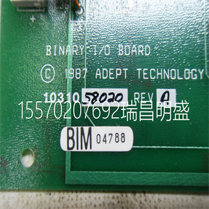
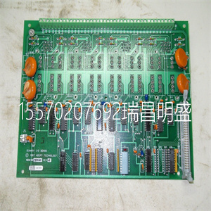
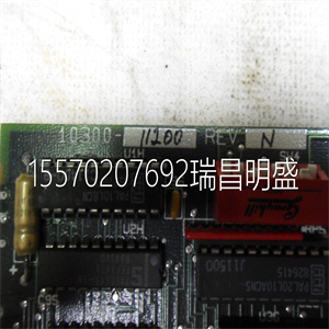


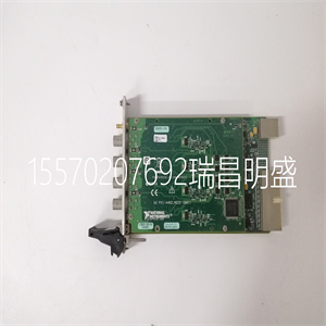
81EA02E GJR2366000R1000 81EA02D-E 伺服驱动板
在Project Explorer硬件树中创建控制器的表示。
确保PM861/PM864/PM865/PM891处理器单元定义为:
冗余的请参阅控件生成器联机帮助。
6.在Project Explorer中,将控制器的IP地址设置为
主CPU。请参阅控件生成器联机帮助。
7.打开辅助CPU。检查您是否与
控制器。
输入/输出系统
有几种方法将I/O系统连接到AC 800M控制器:
•通过CI856的S100输入/输出。
•通过模块总线的S800输入/输出单元。支持运行期间的热配置,
各级冗余、HART路由和事件顺序(SOE)。
•通过CI854/CI854A和CI840/CI840A、PROFIBUS DP的S800输入/输出单元。
支持HART路由、各级冗余和热配置
在运行期间。
如果使用网络冗余,则主设备的CN2端口的IP地址
无法使用IPConfig设置处理器。必须在控制中设置此地址
建设者
如果使用网络冗余,您还必须设置CN2的IP地址
使用IPConfig的备份处理器的端口。请参阅IPConfig联机帮助。
无需在Control Builder中为备份CPU设置IP地址。
备份CPU、CN1和CN2端口的IP地址仅用于
主CPU和备用CPU之间的内部通信。当
备份CPU接管,它还接管定义的主IP地址
在控件生成器中。控制网络上的其他单元永远不会注意到
转换。
3节I/O系统的配置
3BSE036351-510 A 159
•通过CI854/CI854A和CI801、PROFIBUS DP的S800输入/输出单元。支持
HART路由和运行期间的热配置。
•S900输入/输出装置可连接到PROFIBUS DP。
•ABB驱动器可通过CI801和
PM8xx上的模块总线。有些驱动设备可以直接连接
连接到PROFIBUS或PROFINET IO。请参阅特定驱动器
有关更多信息,请参阅文档。
•通过CI862接口的Genius远程I/O(TRIO)
•控制网络上的Satt I/O(19“Satt机架I/O、S200 I/O和S200L I/O),通过
CI865
•通过CI871的PROFINET IO
有关支持的I/O系统和单元的更多信息,请参阅I/O文档。
模块总线
除PM891外,AC 800M控制器中的模块总线包括一个
电气和一个光学单元。PM891仅由光学模块总线组成。
以下是ModuleBus的详细信息:
•电气模块总线(参见160页图54)–1个集群(组),带有
多连接12个S800输入/输出单元。
•光模块总线(参见160页图54)–7个集群(组),具有
多连接7 x 12=84个S800输入/输出单元。
请注意,电气模块总线只能用于连接S800 I/O
当AC 800M以单CPU配置运行时。
PM851/PM851A仅限于一个光模块总线集群。
使用冗余将减少S800信道的大数量。每个
群集多可包含12个单个S800 I/O单元或6个冗余S800 I/O
单位。
81EA02E GJR2366000R1000 81EA02D-E 伺服驱动板
81EA02E GJR2366000R1000 81EA02D-E 伺服驱动板
Create a representation of the controller in the Project Explorer hardware tree.
Make sure the PM861/PM864/PM865/PM891 processor unit is defined as
redundant. See Control Builder online help.
6. In Project Explorer, set the IP address of the controller to the IP address of the
primary CPU. See Control Builder online help.
7. Switch on the secondary CPU. Check that you have communication with the
controller.
I/O Systems
There are several methods of connecting I/O systems to the AC 800M Controller:
• S100 I/O via CI856.
• S800 I/O units via the ModuleBus. Support for hot configuration during run,
redundancy on all levels, HART routing, and Sequence-of-Events (SOE).
• S800 I/O units via CI854/CI854A and CI840/CI840A, PROFIBUS DP.
Support for HART routing, redundancy on all levels, and hot configuration
during run.
If network redundancy is used, the IP address of the CN2 port of the primary
processor cannot be set using IPConfig. This address must be set in Control
Builder
If network redundancy is used, you also have to set the IP address of the CN2
port of the backup processor using IPConfig. See IPConfig online help.
There is no need to set IP address(es) for the backup CPU in Control Builder.
The IP address of the backup CPU, CN1 and CN2 ports will only be used for
internal communication between the primary and backup CPUs. When the
backup CPU takes over, it also takes over the primary IP address that is defined
in Control Builder. Other units on the control network will never notice the
switchover.
Section 3 Configuration I/O Systems
3BSE036351-510 A 159
• S800 I/O units via CI854/CI854A and CI801, PROFIBUS DP. Support for
HART routing, and hot configuration during run.
• S900 I/O units can be connected to PROFIBUS DP.
• ABB Drives can be connected to the ModuleBus, via CI801 and also via
Modulebus on the PM8xx. Some Drives equipment can be connected directly
to PROFIBUS or PROFINET IO. Please refer to Drives-specific
documentation for more information.
• Genius remote I/O (TRIO) via the CI862 Interface
• Satt I/O on ControlNet (19” Satt rack I/O, S200 I/O and S200L I/O) via the
CI865
• PROFINET IO via CI871
For more information on supported I/O systems and units, see I/O documentation.
ModuleBus
The ModuleBus in the AC 800M controller, except PM891, consists of one
electrical and one optical unit. The PM891 consists of optical ModuleBus only.
The following are the details of the ModuleBus:
• Electrical ModuleBus, (see Figure 54 on page 160) – 1 cluster (group), with a
maximum of 12 S800 I/O units connected.
• Optical ModuleBus (see Figure 54 on page 160) – 7 clusters (groups), with
maximum 7 x 12 = 84 S800 I/O units connected.
Note that the electrical ModuleBus can only be used for connection of S800 I/O
when AC 800M is running in single CPU configuration.
PM851/PM851A is restricted to one optical ModuleBus cluster.
Use of redundancy will reduce the maximum number of S800 channels. Each
cluster may contain up to 12 single S800 I/O units or up to 6 redundant S800 I/O
units.
Copyright ©2019-2022 瑞昌明盛自动化设备有限公司 版权所有 赣ICP备2021006016号


