

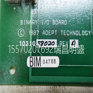
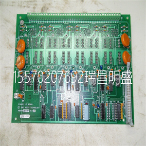


81ET10C GJR2338700R0001 模拟量输出控制板
ABB驱动器可通过CI801和
PM8xx上的模块总线。有些驱动设备可以直接连接
连接到PROFIBUS或PROFINET IO。请参阅特定驱动器
有关更多信息,请参阅文档。
•通过CI862接口的Genius远程I/O(TRIO)
•控制网络上的Satt I/O(19“Satt机架I/O、S200 I/O和S200L I/O),通过
CI865
•通过CI871的PROFINET IO
有关支持的I/O系统和单元的更多信息,请参阅I/O文档。
模块总线
除PM891外,AC 800M控制器中的模块总线包括一个
电气和一个光学单元。PM891仅由光学模块总线组成。
以下是ModuleBus的详细信息:
•电气模块总线(参见160页图54)–1个集群(组),带有
多连接12个S800输入/输出单元。
•光模块总线(参见160页图54)–7个集群(组),具有
多连接7 x 12=84个S800输入/输出单元。
请注意,电气模块总线只能用于连接S800 I/O
当AC 800M以单CPU配置运行时。
PM851/PM851A仅限于一个光模块总线集群。
使用冗余将减少S800信道的大数量。每个
群集多可包含12个单个S800 I/O单元或6个冗余S800 I/O
单位。
I/O系统3节配置
160 3BSE036351-510 A
这总共提供了八个簇(组),大值为8 x 12=96 S800
I/O单元连接到具有单CPU配置的AC 800M控制器。
图54.电气和光学模块总线配置
多7个
集群(组)
多12个输入/输出单元
PM8xx
TB820
TB820
TB820光学
地方的
模块总线
中央/远程
视力的
模块总线
与电有关的
模块总线
(多1个
PM851集群)
3节I/O系统的配置
3BSE036351-510 A 161
在冗余CPU配置中,S800 I/O通过光纤连接
模块总线。每个CPU连接到每个集群上的一个TB840(参见图55
161页)。
图55冗余CPU配置中的光模块总线连接
多7个
集群(组)
多12个输入/输出单元
2 x TB840
2 x TB840
2 x TB840
视力的
地方的
模块总线
中央/远程
冗余CPU
不能使用电气模块总线
I/O系统3节配置
162 3BSE036351-510 A
现场总线DP
PROFIBUS DP段能够提供多达32个节点,可以直接
连接到CI854A/TP854型PROFIBUS DP接口单元。该段可以
可以使用中继器单元进一步扩展。
PROFIBUS PA可通过PROFIBUS链接连接到PROFIBUS DP
装置LD 800P,见附录C,推荐组件。更多详情
请参阅PROFIBUS网站上提供的PROFIBUS文档。
可以将以下I/O系统连接到PROFIBUS DP:
•通过FCI的S800 I/O和/或S800L I/O–参考S800 I/O文档。
•通过FCI CI920的S900输入/输出-参考S900输入输出文件。
•通过现场总线适配器200-APB12的S200 I/O和/或S200L I/O–参考S200
I/O文档。限制适用于PROFIBUS DP。
•其他I/O系统也可连接到PROFIBUS DP。参考
相关制造商文件。
有关各种I/O系统的更多信息,请参阅特定I/O文档。
注意,要在控制器内配置的I/O单元总数可能:
受限制,取决于许可证的单位范围参数。ABB Drives can be connected to the ModuleBus, via CI801 and also via Modulebus on the PM8xx. Some Drives equipment can be connected directly to PROFIBUS or PROFINET IO. Please refer to Drives-specific documentation for more information. • Genius remote I/O (TRIO) via the CI862 Interface • Satt I/O on ControlNet (19” Satt rack I/O, S200 I/O and S200L I/O) via the CI865 • PROFINET IO via CI871 For more information on supported I/O systems and units, see I/O documentation. ModuleBus The ModuleBus in the AC 800M controller, except PM891, consists of one electrical and one optical unit. The PM891 consists of optical ModuleBus only. The following are the details of the ModuleBus: • Electrical ModuleBus, (see Figure 54 on page 160) – 1 cluster (group), with a maximum of 12 S800 I/O units connected. • Optical ModuleBus (see Figure 54 on page 160) – 7 clusters (groups), with maximum 7 x 12 = 84 S800 I/O units connected. Note that the electrical ModuleBus can only be used for connection of S800 I/O when AC 800M is running in single CPU configuration. PM851/PM851A is restricted to one optical ModuleBus cluster. Use of redundancy will reduce the maximum number of S800 channels. Each cluster may contain up to 12 single S800 I/O units or up to 6 redundant S800 I/O units. I/O Systems Section 3 Configuration 160 3BSE036351-510 A This provides a total of eight clusters (groups), with a maximum 8 x 12 = 96 S800 I/O units connected to an AC 800M Controller with single CPU configuration. Figure 54. Electrical and Optical ModuleBus Configuration Maximum of 7 clusters (groups) Maximum of 12 x I/O units PM8xx TB820 TB820 TB820 Optical Local ModuleBus Central/Remote Optical ModuleBus Electrical ModuleBus (Maximum of 1 cluster for PM851) Section 3 Configuration I/O Systems 3BSE036351-510 A 161 In redundant CPU configuration, S800 I/O is connected through the optical ModuleBus. Each CPU is connected to one TB840 on each cluster (see Figure 55 on page 161). Figure 55. Optical ModuleBus connection in redundant CPU configuration Maximum of 7 clusters (groups) Maximum of 12 x I/O units 2 x TB840 2 x TB840 2 x TB840 Optical Local ModuleBuses Central/Remote Redundant CPUs Electrical ModuleBus cannot be used I/O Systems Section 3 Configuration 162 3BSE036351-510 A PROFIBUS DP A PROFIBUS DP segment, capable of providing up to 32 nodes, can be directly connected to a PROFIBUS DP Interface unit type CI854A/TP854. This segment can be further extended using repeater units. PROFIBUS PA can be connected to PROFIBUS DP via the PROFIBUS linking device LD 800P, see Appendix C, Recommended Components. For further details refer to PROFIBUS documentation, available at the PROFIBUS Internet site. It is possible to connect the following I/O systems to the PROFIBUS DP: • S800 I/O and/or S800L I/O via FCI – refer to S800 I/O documentation. • S900 I/O via FCI CI920 - refer to S900 I/O documentation. • S200 I/O and/or S200L I/O via Fieldbus Adapter 200-APB12 – refer to S200 I/O documentation. Restrictions apply for PROFIBUS DP. • Other I/O systems can also be connected to PROFIBUS DP. Refer to the relevant manufacturer’s documentation. For further information on the various I/O systems, see specific I/O documentation. Note that the total number of I/O units to be configured within a controller may be restricted, depending on the unit range parameter of your license.
81ET10C GJR2338700R0001 模拟量输出控制板
81ET10C GJR2338700R0001 模拟量输出控制板
Copyright ©2019-2022 瑞昌明盛自动化设备有限公司 版权所有 赣ICP备2021006016号


