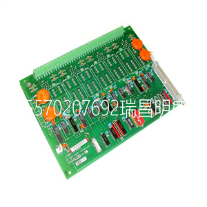
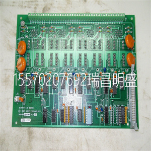


AIO86-8/4 57275812 5760842-1F 模拟接口板模块卡
AC 800M交付时没有控制软件。提供控制器
使用控制软件,首先加载固件,然后创建应用程序
分别使用Control Builder M工程工具。
AC 800M控制器由一系列安装在水平面上的装置组成
DIN导轨,可安装在外壳内。大多数单位包括:
底座安装板和用螺钉连接的可拆卸盖。
底板始终安装在DIN导轨上,承载着大部分
处理器、电源和通信接口的连接
作为到外部总线和系统的连接。
AC 800M控制器为以下方面提供了经济高效、低维护的解决方案:
应用范围从小型可编程逻辑控制器(PLC)到
分布式控制系统(DCS)控制应用和组合DCS,以及
高完整性系统和控制应用。
在AC 800M高完整性控制器中,可以运行非SIL和
SIL分类应用。AC 800M HI由PM865、SM810/SM811组成
以及控制软件的高完整性版本,也可冗余使用
配置AC 800M HI要求使用SIL认证的S800输入/输出单元
除非另有说明,否则PM851等同于PM856。
除非另有说明,否则PM851A等同于PM851。
除非另有说明,否则PM856A等同于PM856。
除非另有说明,否则PM860A等同于PM860
除非另有说明,否则PM861A等同于PM861。
除非另有说明,否则PM864A等同于PM864。
1节AC 800M简介-概述
3BSE036351-510 A 31
分类应用。如果应用程序未进行SIL分类,则标准S800 I/O
装置可与AC 800M HI控制器一起使用。
图1显示了带有
S800输入/输出单元。该物理外观不适用于PM891。
图2显示了作为AC 800M控制器一部分的PM861处理器单元。
该处理器单元不同于PM891。
图1.带有S800 I/O的AC 800M控制器(PM891除外)示例
单元
AC 800M输入/输出系统
S800输入/输出
单元
加工机
单元
表达
界面
AC 800M–概述1节介绍
32 3BSE036351-510 A
图2.处理器单元-总体视图(此处显示为PM861)
发送/接收
光学模块总线
外部电池
电源插座
电源
和
监督信号
插座
COM3/COM4
DIN导轨上的端口
锁定装置
CN1/CN2
港口
发送/接收
地位
初始化
按钮
发光二极管
地位
指标
指标
区域协调股链接
连接器
(PM861/PM864/电气
模块总线
CEX总线
PM865/PM866)
小型闪存插槽
CF连接器
1节PM8xx/TP830处理器单元简介-概述
3BSE036351-510 A 33
PM8xx/TP830处理器单元-概述
物理上,PM8xx/TP830处理器单元由两个基本部分组成:
•处理器单元
(PM851/PM851A/PM856/PM856A/PM860/PM86A/PM861/PM861A)/
PM864/PM864A/PM865/PM866)。
•基板(TP830),用于容纳装置终端板。
有关功能框图,请参见35页图4和
图536页。CPU板包含微处理器和RAM、所有内置通信接口的控制器、实时时钟、LED
指示器、初始化按钮和紧凑型闪存接口。
电源板的主要功能是产生隔离、电路保护
+向CPU和I/O单元提供5V和+3.3V电源。该板还包含用于服务端口的光隔离RS-232C驱动器/接收器,以及一个备份
存储器/实时时钟(RTC)的电池支架。
安装在TP830基板中的终端板是
外部连接终止。电路板通过以下方式接地至DIN导轨:
外壳的金属部件。终端板配有:
用于电源和冗余电源监控的螺钉端子,带
用于控制网络和串行端口的RJ45连接器,用于服务的连接器
端口、电气模块总线和CEX总线。
连接到TP830基板的24V直流电源为
CEX总线和电气模块总线。
在单CPU配置中,它是poss
AIO86-8/4 57275812 5760842-1F 模拟接口板模块卡 
AIO86-8/4 57275812 5760842-1F 模拟接口板模块卡
The AC 800M is delivered without Control Software. To provide the controller
with Control Software, first load the firmware and then create the application
separately using the Control Builder M engineering tool.
The AC 800M Controller consists of a selection of units mounted on horizontal
DIN-rails, which can be housed within an enclosure. The majority of units consist of
a base mounting plate and removable cover attached with screws.
The baseplate, which is always mounted onto the DIN-rail, carries the majority of
the connections to processor, power supplies and communication interfaces, as well
as the connections to the external buses and systems.
The AC 800M Controller provides a cost-effective, low-maintenance solution for
applications ranging from small Programmable Logic Controller (PLC) to advanced
Distributed Control Systems (DCS) control applications and combined DCS, and
High Integrity systems control applications.
In the AC 800M High Integrity Controller, it is possible to run both non-SIL and
SIL classified applications. The AC 800M HI consist of PM865, SM810/SM811
and a High Integrity version of Control Software, and is also available in redundant
configuration. AC 800M HI requires the use of SIL certified S800 I/O units in SIL
PM851 is equivalent with PM856 unless stated otherwise.
PM851A is equivalent with PM851 unless stated otherwise.
PM856A is equivalent with PM856 unless stated otherwise.
PM860A is equivalent with PM860 unless stated otherwise
PM861A is equivalent to PM861 unless stated otherwise.
PM864A is equivalent to PM864 unless stated otherwise.
Section 1 Introduction AC 800M – General
3BSE036351-510 A 31
classified applications. If the application is not SIL classified, standard S800 I/O
units can be used with AC 800M HI controller.
Figure 1 shows the physical appearance of an AC 800M Controller with an
S800 I/O Unit. This physical appearance does not apply to PM891.
Figure 2 shows the PM861 processor unit that is part of the AC 800M controller.
This processor unit is different from PM891.
Figure 1. Example of an AC 800M Controller (except PM891) with an S800 I/O
Unit
AC 800M I/O System
S800 I/O
unit
Processor
unit
Communication
interface
AC 800M – General Section 1 Introduction
32 3BSE036351-510 A
Figure 2. Processor Unit – General View (here shown with PM861)
Tx/Rx
Optical ModuleBus
External Battery
Supply Socket
Power Supply
and
Supervision Signal
Socket
COM3/COM4
Ports DIN-rail
Locking Device
CN1/CN2
Ports
Tx/Rx
Status
INIT
Push button
LED
Status
Indicators
Indicators
RCU Link
Connector
(PM861/PM864/ Electrical
ModuleBus
CEX-Bus
PM865/PM866)
Compact Flash slot
CF Connector
Section 1 Introduction PM8xx/TP830 Processor Unit – General
3BSE036351-510 A 33
PM8xx/TP830 Processor Unit – General
Physically the PM8xx/TP830 Processor Unit consists of two basic parts:
• Processor Unit
(PM851/PM851A/PM856/PM856A/PM860/PM860A/PM861/PM861A/
PM864/PM864A/PM865/PM866) with processor and Power Supply boards.
• Baseplate (TP830), housing the unit termination board.
For the Functional Block Diagram, see Figure 4 on page 35 and
Figure 5 on page 36. The CPU board contains the microprocessor and the RAMmemory, controllers for all built-in communication interfaces, real-time clock, LED
indicators, INIT push button and a Compact Flash interface.
The main function of the power supply board is to generate isolated, circuit-proof
+5 V and +3.3 V supplies to the CPU and I/O units. The board also contains optoisolated RS-232C drivers/receivers for the service port, together with a back-up
battery holder for memory/real time clock, (RTC).
The termination board, housed in the TP830 Baseplate, is where the majority of
the external connections terminates. The board is grounded to the DIN-rail through
of the metallic components of the housing. The termination board is provided with
screw terminals for power supply and redundant power supply monitoring, with
RJ45 connectors for the control network and serial port, a connector for the service
port, the electrical ModuleBus and the CEX-Bus.
The 24 V DC supply, connected to the TP830 Baseplate, powers all the units on the
CEX-Bus and the electrical ModuleBus.
In single CPU configuration, it is poss
AIO86-8/4 57275812 5760842-1F 模拟接口板模块卡
Copyright ©2019-2022 瑞昌明盛自动化设备有限公司 版权所有 赣ICP备2021006016号


