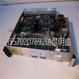
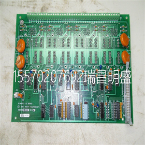


Bailey Infi 90 多功能处理器模块 IMMFP02 IMMFP 02
在单个配置中安装PM891
使用以下步骤以单一配置安装PM891处理器单元:
1.如果已经连接,则从
PM891处理器单元。
2.安装PM891处理器单元、通信接口和S800
DIN导轨上的I/O装置。
PM891的通信接口连接到CEX总线
处理器单元的左侧。PM891的S800输入/输出单元通过以下方式连接:
处理器单元底部的光学模块总线。
3.将总线终端重新插入距离
处理器单元。对于CEX总线,使用TB850终端插头(TB851,如果
使用CEX总线延长电缆TK850。如果在CEX总线上没有使用单元,
不需要总线终端。
4.使用终端插头提供冗余终端
TB853 RCU控制链路端子,位于
处理器单元的顶部。
5.提供电缆连接:
a、 将电源引线连接到螺钉端子L+和L-。如果适用,
将SS82x的电源监控信号连接到螺钉端子
SA和SB。
b、 将控制网络电缆连接至CN1(单连接),或
CN1+CN2(冗余连接)。
c、 使用电缆TK212将控制构建器连接到COM4(如果需要,用于
改变IP地址)。否则,将控件生成器连接到
控制网络。
在单个配置中安装PM8912节安装
88 3BSE036351-510 A
6.将光学模块总线连接至底部的光学触点(Tx1/Rx1)
处理器单元(参见43页图10)。关于
光缆选择和电缆长度,请参阅S800 I/O文档。
7.通过将PM891单元连接到外部SB822提供备用电池
电池单元。按照安装SB822中的说明进行安装
144页的可充电外部电池单元。
通信端口-CN1和CN2
控制网络连接到一个或两个RJ45连接器(CN1和CN2)
取决于网络选项(单个或冗余)。
使用IEEE802.3(以太网)的RJ45连接器连接到5类
屏蔽双绞线(STP 5级)。
光学模块总线的连接与处理器单元的连接相同
对于S800 I/O中的FCI(参见160页的图54)
5级或更高,电缆10/100BaseT/TX大100米(110码)。ABB建议:
在工业环境中使用光纤,例如62.5/125
100BaseFX,大距离1500米(1600码)。
表8.TP830 CN1和CN2连接(RJ45连接器)
引脚名称方向描述
1 TD+输出传输数据(plus)
2 TD-输出传输数据(减)
接收数据中的3+条(加号)
4–5–未使用
6位-接收数据中(减)
7–8–未使用
外壳屏蔽-屏蔽
2节安装:在单个配置中安装PM891
3BSE036351-510 A 89
COM4端口
COM4端口是一个RS-232C端口,光隔离,没有调制解调器信号。
当直接连接到控制器时,将控件生成器连接到此端口,
或者,当不需要时,无需通过
控制网络。
表9.PM891 COM4连接(RJ45连接器)
引脚名称方向描述
1–未使用
2–未使用
3 TD输出传输数据
4.0 V–信号接地
5.0 V–信号接地
接收数据中的6位
7–未使用
8–未使用
外壳屏蔽-屏蔽
在冗余配置中安装PM86x/TP830处理器单元2节:安装
90 3BSE036351-510 A
冗余安装PM86x/TP830处理器单元
配置
在冗余配置中,安装了两个PM861/PM864/PM865/PM866单元
安装在两个单独的DIN导轨上。如果有足够的空间,单元可以
安装在同一DIN导轨上
使用以下步骤沿DIN导轨安装处理器单元:
1.安装处理器单元。
2.将通信接口安装在CEX总线左侧
处理器单元。如果使用BC810,则段的配置应为
考虑过的。如果未使用BC810,则接口可在
以任何优选方式提供两个CPU。
3.轻轻地将单元压在一起,确保CEX总线正确
通过基板上的连接器连接。
4.如果使用BC810,将TK851电缆连接到两个BC810(图31
100页)。如果未使用BC810,则安装CEX总线延长电缆TK850
到离处理器单元远的单元,或者,如果没有单元
直接安装到处理器单元上的CEX总线。CEX巴士
无论是否有任何CPU,扩展电缆必须连接到两个CPU
其他CEX总线单元(93页图29)。
本主题不适用于冗余PM891装置的安装
配置请参阅以冗余方式安装PM891处理器单元
配置见94页。
注意,在冗余CPU配置中,COM3和电气模块总线
底板上不能使用
Bailey Infi 90 多功能处理器模块 IMMFP02 IMMFP 02
Bailey Infi 90 多功能处理器模块 IMMFP02 IMMFP 02
Installing pm891 in a single configuration
Use the following steps to install the pm891 processor unit in a single configuration:
1. If it is already connected, start from
Pm891 processor unit.
2. Install pm891 processor unit, communication interface and S800
I / O unit on DIN rail.
The communication interface of pm891 is connected to the CEX bus
The left side of the processor unit. S800 I / O unit of pm891 is connected in the following way:
Optical module bus at the bottom of the processor unit.
3. Reinsert the bus terminal into the distance
Processor unit. For CEX bus, use tb850 terminal plug (tb851, if
Use the CEX bus extension cable TK850. If no unit is used on the CEX bus,
No bus terminal is required.
4. Use terminal plug to provide redundant terminals
Tb853 RCU control link terminal, located at
The top of the processor unit.
5. Provide cable connection:
a. Connect the power lead to the screw terminals L + and L -. If applicable,
Connect the power monitoring signal of ss82x to the screw terminal
SA and sb.
b. Connect the control network cable to cN1 (single connection), or
CN1 + cn2 (redundant connection).
c. Connect the control builder to COM4 using cable tk212 (for
Changing the IP address). Otherwise, connect the control generator to
Control network.
Installing pm891 in a single configuration section 2 installation
88 3BSE036351-510 A
6. Connect the optical module bus to the optical contact (TX1 / rx1) at the bottom
Processor unit (see Figure 10 on page 43). about
Please refer to S800 I / O documentation for cable selection and cable length.
7. Provide backup battery by connecting pm891 unit to external sb822
Battery cells. Follow the instructions in installing sb822
Rechargeable external battery unit on page 144.
Communication ports - cN1 and cn2
The control network is connected to one or two RJ45 connectors (cN1 and cn2)
Depending on the network options (single or redundant).
Use RJ45 connector of IEEE802.3 (Ethernet) to connect to class 5
Shielded twisted pair (STP class 5).
The connection of the optical module bus is the same as that of the processor unit
For FCI in S800 I / O (see Figure 54 on page 160)
Class 5 or higher, cable 10 / 100BaseT / TX max. 100m (110 yards). ABB recommends:
Use of optical fibers in industrial environments, e.g. 62.5/125
100BaseFX, maximum distance 1500 meters (1600 yards).
Table 8. Tp830 cN1 and cn2 connection (RJ45 connector)
Pin name direction description
1 TD + output transmission data (plus)
2 TD output transmission data (minus)
Item 3 + in received data (plus sign)
4 – 5 – not used
Bit 6 - received data (minus)
7 – 8 – not used
Enclosure shield - Shield
Section 2 installation: installing pm891 in a single configuration
3BSE036351-510 A 89
COM4 port
COM4 port is an RS-232C port with optical isolation and no modem signal.
When directly connected to the controller, connect the control generator to this port,
Or, when not needed, no need to pass
Control network.
Table 9. Pm891 COM4 connection (RJ45 connector)
Pin name direction description
1 – not used
2 – not used
(3) TD output transmission data
4.0 V – signal ground
5.0 V – signal ground
The 6th bit in the received data
7 – not used
8 – not used
Enclosure shield - Shield
Installing a pm86x / tp830 processor unit in a redundant configuration section 2: installing
90 3BSE036351-510 A
Redundant installation of pm86x / tp830 processor unit
to configure
In the redundant configuration, two pm861 / pm864 / pm865 / pm866 units are installed
Mounted on two separate DIN rails. If there is enough space, the unit can
Mounted on the same DIN rail
Use the following steps to install the processor unit along the DIN rail:
1. Install the processor unit.
2. Install the communication interface on the left side of CEX bus
Processor unit. If bc810 is used, the configuration of the segment should be
I have considered it. If bc810 is not used, the interface can be
Two CPUs are provided in any preferred manner.
3. Gently press the units together to ensure that the CEX bus is correct
Connected through the connector on the base plate.
4. If bc810 is used, connect TK851 cable to two bc810s (Figure 31
Page 100). If bc810 is not used, install the CEX bus extension cable TK850
To the unit farthest from the processor unit, or if there is no unit
CEX bus directly mounted to the processor unit. CEX bus
Whether there are any CPUs or not, the expansion cable must be connected to both CPUs
Other CEX bus units (Figure 29 on page 93).
This topic is not applicable to the installation of redundant pm891 units
For configuration, see installing the pm891 processor unit redundantly
See page 94 for configuration.
Note that in redundant CPU configuration, COM3 and electrical module bus
Cannot be used on the base plate
Bailey Infi 90 多功能处理器模块 IMMFP02 IMMFP 02
Copyright ©2019-2022 瑞昌明盛自动化设备有限公司 版权所有 赣ICP备2021006016号


