


SBL4-0260-2-24 T0BPV 输出模块用于控制传输速度 Kollmorgen
将锁定装置旋转至装置底板上的滑动位置(2),
参见第69页的图17。
4.轻轻地从侧面松开装置/底板,以释放
正在拆除装置底板。
5.逆时针转动锁紧装置至打开位置(1),并松开
装置底板在底座处向外和向上。提起装置,将其从
DIN导轨。AC 800M装置必须与电源断开连接
然后将其从DIN导轨上拆下。
为了提供足够的进入和拆卸空间,请注意,滑块
必须在与装置相邻的装置基板上执行顺序,即:
将被移除。
通过轻轻撬动,装置底板可以轻松地彼此断开
用一字螺丝刀将它们分开(参见第74页图23)。
预制铝型材第2节安装
74 3BSE036351-510 A
图23.分离底板
F
R
接收/发送
实时战略
F
R
Rx1
Tx1
Rx2
Tx2
CI853
COM1和COM2
F
R
P
初始化
B
PM860
CN1 CN2 COM3 COM4
CI851
第二节预制铝型材安装
3BSE036351-510 A 75
装置至基板阿尔法密码锁
底板具有预设的阿尔法码锁定装置。该锁定装置防止:
在基板上安装不兼容类型的装置,如果Alpha代码
不匹配。所有相同的装置类型都具有相同的出厂预设值,两个字母α
交付前安装的代码。
以下装置类型安装了两部分预设阿尔法码锁定装置
(见第75页表4)。
表4.工厂预设阿尔法代码
装置键位置1键位置2
CI851现场总线DP
界面
A A
CI852基金会现场总线
H1接口
A、B
CI853 RS-232C接口A C
CI854/CI854A现场总线DP
界面
A D
CI855以太网接口
MasterBus 300
A、E
CI856 S100接口B A
CI857 INSUM接口B B B
CI858驱动总线接口B C
CI860基金会现场总线
高速以太网
(FF HSE)接口。
B、E
CI862 TRIO/Genius接口(无阿尔法锁定)(无阿尔法锁)
CI865 Satt输入/输出C F
CI867 Modbus TCP接口D(1)B(1)
CI868 IEC 61850接口D(1)B(1)
预制铝型材第2节安装
76 3BSE036351-510 A
有关预设Alpha代码的更多详细信息,请参阅相关装置文件。
参见第77页图24,了解阿尔法码锁布置的更多细节。
机械钥匙是预设的,不得更改。这防止了
可拆卸接口放置在错误类型的底板上。
CI869 AF 100接口D C
CI872 MOD5接口D E
CI871 PROFINET IO接口D(1)B(1)
CI873以太网/IP设备网
界面
D(1)B(1)
BC810 CEX总线
互连单元
答
SM810 C B
SM811 D D
S800各种输入/输出装置–参见S800输入/输出
产品/用户指南
各种–参见S800输入/输出
产品/用户指南
(1) 关键位置对于CI867、CI868、CI871和CI873是通用的。因此必须谨慎
进行现场更换。确保插入正确的CI,特别是在热插入时。
确保基板和待安装装置具有兼容的Alpha代码。
否则可能导致设备损坏。在设备上安装装置有任何困难吗
特定底板指示阿尔法码锁定的差异。
不要操纵锁定装置。ABB将不承担以下责任:
操作锁定装置引起的错误。
表4.工厂预设阿尔法代码(续)
装置键位置1键位置2
第二节预制铝型材安装
3BSE036351-510 A 77
图24.装置底板-阿尔法码锁布置
预设
字母代码键
在单个配置中安装PM86x/TP830处理器单元第2节:安装
78 3BSE036351-510 A
在单个中安装PM86x/TP830处理器单元
配置
按照以下步骤沿DIN导轨安装处理器单元:
1.如果已经安装,则从
处理器单元的侧面。
2.安装处理器单元、通信接口和S800 I/O
单位。
所有PM8xx的通信接口均位于左侧的CEX总线上
处理器单元。PM8xx的S800输入/输出单元位于电气上
处理器单元右侧的模块总线。
3.轻轻地将它们压在一起,并确保ModuleBus和CEXBus通过基板连接器正确连接。
4.将总线终端重新插入远的通信单元
来自处理器单元。
a、 对于CEX总线TB850(如果使用电缆TK850,则为TB851),参见图25
第80页和第81页的图26。使用BC810时,请参见
第82页。如果在CEX总线上未使用任何单元,则不使用总线终端
必修的。
b、 有关ModuleBus TB807,请参阅S800 I/O文档。如果没有单位
如果在模块总线上使用,则不需要总线终端。
本主题不适用于PM891处理器单元。请参阅中的安装PM891
第87页的单一配置。
对于PM861/PM864/PM865/PM866,插入RCU链路终端插头
TB852,位于RCU链路连接器处。终端插头必须始终
SBL4-0260-2-24 T0BPV 输出模块用于控制传输速度 Kollmorgen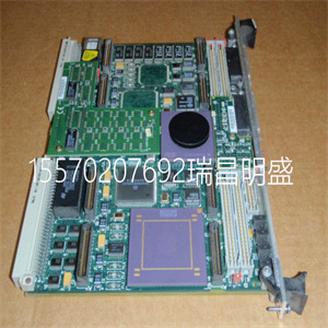
vSBL4-0260-2-24 T0BPV 输出模块用于控制传输速度 Kollmorgen
Rotate the locking device to the SLIDE position (2) on the unit baseplate,
see Figure 17 on page 69.
4. Gently ease the unit/baseplates sideways in order to release the contacts of the
unit baseplate being removed.
5. Turn the locking device anti-clockwise to the OPEN position (1) and ease the
unit baseplate outward and upward at the base. Lift the unit to remove it from
the DIN-rail. The AC 800M units must be disconnected from the power source
before removing them from the DIN-rail.
In order to provide adequate access and removal space, note that the SLIDE
sequence must be carried out on the unit baseplates adjacent to the unit that is
to be removed.
The unit baseplates are easily disconnected from each other by gently prying
them apart with a blade screwdriver (see Figure 23 on page 74).
Prefabricated aluminum profile Section 2 Installation
74 3BSE036351-510 A
Figure 23. Separating the Baseplates
F
R
Rx/Tx
RTS
F
R
Rx1
Tx1
Rx2
Tx2
CI853
COM1 COM2
F
R
P
INIT
B
PM860
CN1 CN2 COM3 COM4
CI851
Section 2 Installation Prefabricated aluminum profile
3BSE036351-510 A 75
Unit to Baseplate Alpha Code Lock
Baseplates have a pre-set Alpha code locking device. This locking device prevents
the installation of an incompatible type of unit onto the base plate if the Alpha codes
do not match. All identical unit types have the same factory pre-set, two-letter Alpha
code installed prior to delivery.
The following unit types have two-part, pre-set Alpha code locking devices installed
(see Table 4 on page 75).
Table 4. Factory Pre-set Alpha Codes
Unit Key Position 1 Key Position 2
CI851 PROFIBUS DP
Interface
A A
CI852 FOUNDATION Fieldbus
H1 Interface
A B
CI853 RS-232C Interface A C
CI854/CI854A PROFIBUS DP
Interface
A D
CI855 Ethernet interface for
MasterBus 300
A E
CI856 S100 interface B A
CI857 INSUM Interface B B
CI858 DriveBus Interface B C
CI860 FOUNDATION Fieldbus
High Speed Ethernet
(FF HSE) Interface.
B E
CI862 TRIO/Genius Interface (no Alpha lock) (no Alpha lock)
CI865 Satt I/O C F
CI867 Modbus TCP Interface D(1) B(1)
CI868 IEC 61850 Interface D(1) B(1)
Prefabricated aluminum profile Section 2 Installation
76 3BSE036351-510 A
For further details on pre-set Alpha codes, refer to the relevant unit documentation.
See Figure 24 on page 77 for further details of the Alpha code lock arrangement.
The mechanical keys are delivered pre-set and must not be altered. This prevents the
removable interface being placed on the wrong type of baseplate.
CI869 AF 100 Interface D C
CI872 MOD5 Interface D E
CI871 PROFINET IO Interface D(1) B(1)
CI873 EtherNet/IP DeviceNet
Interface
D(1) B(1)
BC810 CEX-Bus
Interconnection Unit
C A
SM810 C B
SM811 D D
S800 I/O Units Various – see S800 I/O
Product/User’s Guide
Various – see S800 I/O
Product/User’s Guide
(1) The key positions are common to CI867, CI868, CI871 and CI873. Hence caution must be
exercised in field replacement. Ensure that correct CI is inserted, especially in hot insert.
Ensure that the baseplate and the unit to be mounted have compatible Alpha codes.
Otherwise it may result in equipment damage. Any difficulty in installing a unit on a
particular baseplate indicates a difference in Alpha Code lock.
Do not manipulate the locking device. ABB will take no responsibility for
errors caused by manipulating locking devices.
Table 4. Factory Pre-set Alpha Codes (Continued)
Unit Key Position 1 Key Position 2
Section 2 Installation Prefabricated aluminum profile
3BSE036351-510 A 77
Figure 24. Unit Baseplate – Alpha Code Lock Arrangement
Pre-Set
Alpha Code Keys
Installing the PM86x/TP830 Processor Unit in Single Configuration Section 2 Installation
78 3BSE036351-510 A
Installing the PM86x/TP830 Processor Unit in Single
Configuration
Use the procedure below to install the processor unit along the DIN-rail:
1. If already mounted, remove the CEX-Bus and ModuleBus terminations from
the sides of the processor unit.
2. Mount the processor unit, the communication interfaces, and the S800 I/O
units.
The communication interfaces for all PM8xx is on the CEX-Bus to the left of
the processor unit. The S800 I/O units for PM8xx is on the electrical
ModuleBus to the right of the processor unit.
3. Press them gently together and make sure that the ModuleBus and the CEXBus are correctly connected, via baseplate connectors.
4. Reinsert the bus terminations into the communication units at farthest away
from the processor unit.
a. For CEX-Bus TB850 (TB851 if cable TK850 is used), see Figure 25 on
page 80 and Figure 26 on page 81. When using BC810, see Figure 27 on
page 82. If no units are used on the CEX-Bus, no bus termination is
required.
b. For ModuleBus TB807, refer to the S800 I/O documentation. If no units
are used on the ModuleBus, no bus termination is required.
This topic does not apply to the PM891 processor unit. See Installing PM891 in
Single Configuration on page 87.
For PM861/PM864/PM865/PM866 insert the RCU Link Termination plug
TB852, at the RCU Link connector. The termination plug must always be used
for PM861/PM864/PM865/PM866 when running in single configuration.
When a redundant processor is running in a single configuration use the RCU
Link Cable TK851, if the RCU Link Termination plug TB852 is not available
SBL4-0260-2-24 T0BPV 输出模块用于控制传输速度 Kollmorgen
Copyright ©2019-2022 瑞昌明盛自动化设备有限公司 版权所有 赣ICP备2021006016号


