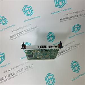
HIEE300024R4 UAA326A04 UAA326 A04 模拟量输出卡 ABB
系统可具有多组过滤器以去除不同水平的杂质。
2.冷却盘管和加热盘管的布置可能因单元而异。
3.冷却盘管可能不存在于每个机组中,也可能位于外部空气风门之前,用于预冷却。
4.加热线圈可能不存在于每个单元中。
5.主加热盘管可能位于管道系统中较远的线路下方,称为再热。重新加热
盘管将在空气从管道排出之前加热特定空间的空气。
6.系统可以利用旁路设置,其中如果不需要,空气可以转向通过盘管
治疗。
7.加湿管可能不在每个单元中,也可能在之前在管道系统中更远的位置
扩散器。
8.如果送风机产生足够的吸力来抽吸空气,则每个机组上可能不存在回风机
穿过太空。
加热/冷却系统
组件/布局:
阻尼器
过滤器
加热线圈
冷却盘管
加湿净化器
送风机
回风机
空气流量:
这种类型的装置常见于空气中的水分去除量不大的环境
涉及从外部空气入口开始,空气进入外部空气管道,并与来自
过滤器(B)前的空间。该混合空气被吸入一组过滤器,其中杂质被去除。这个
然后,空气经过一组加热线圈(C),必要时,在那里被加热到所需温度。下一个
空气通过一组冷却盘管(D);在这里,如有必要,可将其合理地冷却至所需温度。之后
在冷却盘管中,空气经过一组加湿管。如果空气的相对湿度太低
管道会在空气通过时增加水分。在加湿器之后,空气被吸入送风机(F),送风机
推动其通过供水管网、扩散器并进入空间。回风机(G)将吸入空气
并将其推过回流管道系统。空气被排出或返回至待处理装置
与外部空气混合,重新开始循环。
制冷剂/供暖供应:
冷却盘管来自冷却源,如冷却器、冷却塔或DX装置。制冷剂
进入冷却盘管,从通过盘管的空气中吸收热量,并返回热源以解吸热量
IPI在环境中实施可持续节能战略的方法(2017年)
11
它接受了。
加热线圈由热源(例如锅炉或电力)供给。来自这些线圈的热量被传递
对经过它的空气。
系统变化:
1.系统可以具有多组过滤器以去除不同水平的杂质。
2.冷却盘管可位于外部空气风门之前,用于预冷却。
3.系统可利用旁路设置,其中如果不需要,空气可转向通过盘管
被治疗。
4.加湿管可能不在每个单元中,也可能在之前在管道系统中更远的位置
扩散器。
5.如果送风机产生足够的吸力来抽吸空气,则每个机组上可能不存在回风机
通过系统返回
HIEE300024R4 UAA326A04 UAA326 A04 模拟量输出卡 ABB

HIEE300024R4 UAA326A04 UAA326 A04 模拟量输出卡 ABB
A system may have multiple sets of filters to remove different levels of impurities.
2. The arrangement of the cooling coil and heating coil may vary from unit to unit.
3. A cooling coil may not be present in every unit or may be before the outside air dampers for precooling.
4. A heating coil may not be present in every unit.
5. The main heating coil may be farther down the line in the ductwork in what is called a reheat. As a reheat
the coil will heat air for a specific space just before it is discharged from the ducts.
6. A system may utilize a bypass setup where the air can be diverted past the coil(s) if it does not need to be
treated.
7. Humidification tubes may not be present in every unit or may be farther down in the ductwork just before
the diffusers.
8. A return fan may not be present on every unit if the supply fan creates enough of a draw to pull the air
back through the space.
Heating/Cooling System
Components/Layout:
Dampers
Filters
Heating Coil
Cooling Coil
Humidifier
Supply Fan
Return Fan
Air Flow:
This type of unit is most common in environments where moisture removal from the air is not much of a
concern. Starting at the outside air intake, air enters the outside air duct and is mixed with return air from the
space just before the filters (B). This mixed air is pulled through a set of filters where impurities are removed. The
air then passes over a set of heating coils (C) where it is heated to the required temperature if necessary. Next the
air passes over a set of cooling coils (D); here it is sensibly cooled to the desired temperature if necessary. After
the cooling coil the air passes over a set of humidification tubes. If the relative humidity of the air is too low these
tubes will add moisture to the air as it passes. After the humidifiers, the air is pulled into the supply fan (F), which
pushes it through the supply ductwork, through the diffusers and into the space. The return fan (G) will pull in air
from the space and push it through the return ductwork. The air is either exhausted or returned to the unit to be
mixed with outside air and start the cycle all over again.
Refrigerant/Heating Supply:
The cooling coils are fed from a source of cooling, such as chillers, a cooling tower, or DX unit. The refrigerant
enters the cooling coils, absorbs heat from the air passing the coils, and returns to the source to desorb the heat
IPI’s Methodology for Implementing Sustainable Energy-Saving Strategies in Collections Environments (2017)
11
that it took in.
The heating coils are fed from a heat source such as a boiler or electricity. The heat from these coils is transferred
to the air passing over it.
System Variations:
1. A system may have multiple sets of filters to remove different levels of impurities.
2. A cooling coil may be before the outside air dampers for pre-cooling.
3. The system may utilize a bypass setup where the air can be diverted past the coil(s) if it does not need to
be treated.
4. Humidification tubes may not be present in every unit or may be farther down in the ductwork just before
the diffusers.
5. A return fan may not be present on every unit if the supply fan creates enough of a draw to pull the air
back through the system
HIEE300024R4 UAA326A04 UAA326 A04 模拟量输出卡 ABB