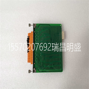
NSV 02 44209-710.01 应用于控制系统电源模块 GRUNDIG
0:零集。当位从“0”变为“1”时,执行零设置。
–1卷的零组,或
–如果选择分段滚动,则所有称重传感器的零集。
1位:零集。当位从“0”变为“1”时,执行零设置。
–2卷的零组
2位:增益调度。
–如果位设置为“0”,则使用回绕增益参数1
–如果位设置为“1”,则使用回绕增益参数2
数据字节号。
一点也不。
76543210
布尔输出017、6、5、4、3、2、1、0
02备用
张力电子PFEA113,用户手册
三章调试
3-48 3 BSE029382R0101版本C
3.14可选装置的调试
3.14.1绝缘放大器PXUB 201
绝缘放大器连接到张力电子装置电压输出。
S1通常设置为电压1:1比。
选择输出以通过开关S1和S2产生电压或电流输出。
通过开关S2(位置3)选择较慢的响应。
开关位于装置内部。
图3-27绝缘放大器PXUB 201
必须打开绝缘放大器才能设置开关S1和S2。
1.从DIN导轨上卸下绝缘放大器。
使用螺丝刀卸下绝缘放大器底部的弹簧。
2.按下绝缘放大器两侧的卡锁。
3.打开顶盖,直到看到开关S1和S2。
S2
1 2 3
上
S1
1 2 3
上
顶盖
快锁,快锁
拉出顶盖,
释放后
弹簧锁。
释放弹簧锁
张力电子PFEA113,用户手册
3.14.1节绝缘放大器PXUB 201
3BSE029382R0101版本C 3-49
4.设置开关S1和S2。
5.将顶盖滑回锁定位置。
6.将绝缘放大器重新安装在DIN导轨上。
图3-28绝缘放大器的典型连接
表3-7.输入和输出范围的设置
违约
范围S1至S2
输入输出1 2 3 1 2 3
0至±10 V 0至±10V
0至5 V 4至20 mA×
0至10 V 4至20 mA×
0至5 V 0至20 mA×
0±10 V 0±20 mA×
世界
世界
信号
0V
+24伏
0V
+
-
+
-
+ 5
6.
3.
4.
7.
8.
信号
0V
+24伏
0V
+
-
+
-
+
–
5.
6.
3.
4.
7.
8.
PXUB 201
PXUB 201
– 1 2 3
上
S1
1 2 3
上
S2
1 2 3
上
S1
1 2 3
上
S2
输出:4至20 mA
输入:0至10 V
输出:0至±10 V
输入:0至±10 V
张力电子PFEA113,用户手册
三章调试
3-50 3BSE029382R0101版本C
多可安装四个PXUB 201或PXKB 201(A、B、C和D),如下图所示
PFEA113内部(IP65版本)。
PXUB 201输出根据订单预设为出厂电压或电流
信息
表3-8.带宽设置
默认带宽S2,位置3
(×=ON)
×10千赫
10赫兹×
四个PXUB 201或PXKB 201
张力电子PFEA113,用户手册
关于本章的4.1节
3BSE029382R0101版本C 4-1
四章操作
4.1关于本章
在正常操作期间,您的测量系统不需要任何注意。测量
只要系统打开,就可以连续运行。但是,您需要知道如何启动
并关闭系统,参见4.4节启动和关闭。
4.2安全说明
在开始任何操作之前,请阅读并遵循1章介绍中给出的安全说明
操作工作。然而,如果当地法规更严格,则应优先考虑。
4.3操作装置
LED指示灯和操作员键如图4-1所示。
图4-1.操作设备
电源状态
背光LCD显示器
后退,后退,上升,正常(确认)
LED“电源”LED“状态”
或取消
张力电子PFEA113,用户手册
四章操作
BSE029382R0101版本C
4.4启动和关闭
4.4.1启动
使用外部开/关开关(未提供)启动和关闭张力电子设备
由ABB提供)。正常操作期间,无需操作员采取任何行动。
1.检查主张力控制机械是否准备好正常运行。
2.通过将外部on/OFF开关设置为on位置,打开张力电子设备。
对于IP 65版本(NEMA 4),也将内部开关设置为“开”。
3.检查:
-显示屏亮起
-“电源”指示灯点亮
-“状态”指示灯点亮(绿灯)。红灯表示错误。
4.4.2关闭
通过将外部开/关开关设置为关闭位置,关闭张力电子设备。
4.5正常运行
测量设备应开启,以获得佳测量结果。
这允许称重传感器和电子设备在稳定的温度条件下工作。
测量设备设计用于连续操作。
电源状态
“功率”指示器
陈列
“状态”指示器
张力电子PFEA113,用户手册
4.6节显示器上的测量值
3BSE029382R0101版本C 4-3
4.6显示器上的测量值
根据所选单位,th
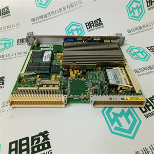
NSV 02 44209-710.01 应用于控制系统电源模块 GRUNDIG

NSV 02 44209-710.01 应用于控制系统电源模块 GRUNDIG
0: Zero Set. Zero set is performed when the bit is changed from “0” to “1”.
– Zero set of Roll 1 or
– Zero set of all load cells if Segmented roll is selected.
Bit No. 1: Zero Set. Zero set is performed when the bit is changed from “0” to “1”.
– Zero set of Roll 2
Bit No. 2: Gain Scheduling.
– Wrap gain parameter 1 is used if the bit is set to “0”
– Wrap gain parameter 2 is used if the bit is set to “1”
Data Byte No.
Bit No.
76543210
Boolean out 01 No. 7 No. 6 No. 5 No. 4 No. 3 No. 2 No. 1 No. 0
02 Spare for future use
Tension Electronics PFEA113, User Manual
Chapter 3 Commissioning
3-48 3BSE029382R0101 Rev C
3.14 Commissioning of Optional Units
3.14.1 Insulation Amplifier PXUB 201
The insulation amplifier is connected to the tension electronics voltage output.
S1 is normally set for voltage 1:1 ratio.
The output is selected to generate a voltage or current output by means of switch S1 and S2.
Slower response is selected by means of switch S2, position 3.
The switches are located inside the unit.
Figure 3-27. Insulation Amplifier PXUB 201
You must open the insulation amplifier to be able to set the switches S1 and S2.
1. Demount the insulation amplifier from the DIN rail.
Use a screw driver to unload the spring at the bottom of the insulation amplifier.
2. Press down the snap-locks on both sides of the insulation amplifier.
3. Pull the top lid open, until you see both the switches S1 and S2.
S2
1 2 3
ON
S1
1 2 3
ON
Top lid
Snap-lock Snap-lock
Pull out the top lid,
after releasing
the snap-locks.
To release Spring lock
Tension Electronics PFEA113, User Manual
Section 3.14.1 Insulation Amplifier PXUB 201
3BSE029382R0101 Rev C 3-49
4. Set the switches S1 and S2.
5. Slide back the top lid to locked position.
6. Remount the insulation amplifier on the DIN rail.
Figure 3-28. Typical Connection of the Insulation Amplifier
Table 3-7. Setting of Input and Output Range
Default
Range S1 S2
Input Output 1 2 3 1 2 3
× 0 to ±10 V 0 to ±10 V × ×
0 to 5 V 4 to 20 mA ×
0 to 10 V 4 to 20 mA ×
0 to 5 V 0 to 20 mA × ×
0 ± 10 V 0 ± 20 mA ×
Earth
Earth
Signal
0 V
+24 V
0 V
+
-
+
-
+ 5
6
3
4
7
8
Signal
0 V
+24 V
0 V
+
-
+
-
+
–
5
6
3
4
7
8
PXUB 201
PXUB 201
– 1 2 3
ON
S1
1 2 3
ON
S2
1 2 3
ON
S1
1 2 3
ON
S2
Output: 4 to 20 mA
Input: 0 to 10 V
Output: 0 to ± 10 V
Input: 0 to ± 10 V
Tension Electronics PFEA113, User Manual
Chapter 3 Commissioning
3-50 3BSE029382R0101 Rev C
Up to Four PXUB 201 or PXKB 201 (A, B, C and D), see the figure below, can be mounted
inside the PFEA113 (IP65-version).
The PXUB 201 outputs are pre-set to either voltage or current from factory according to order
information.
Table 3-8. Setting of Bandwidth
Default Bandwidth S2, position 3
(× = ON)
× 10 kHz
10 Hz ×
Four PXUB 201 or PXKB 201
Tension Electronics PFEA113, User Manual
Section 4.1 About this Chapter
3BSE029382R0101 Rev C 4-1
Chapter 4 Operation
4.1 About this Chapter
Your measurement system does not need any attention during normal operation. Measurement
runs continuously as long as the system is switched on. However, you need to know how to start
and shut down the system, see Section 4.4 Start-up and shut-down.
4.2 Safety Instructions
Read and follow the safety instructions given in Chapter 1 Introduction, before starting any
operation work. However, local statutory regulations, if stricter, are to take precedence.
4.3 Operating Devices
The LED-indicators and operator keys are described in Figure 4-1.
Figure 4-1. Operating Devices
Power Status
Backlit LCD display
Step back Step down Step up OK (acknowledgment)
LED “Power” LED “Status”
or cancel
Tension Electronics PFEA113, User Manual
Chapter 4 Operation
4-2 3BSE029382R0101 Rev C
4.4 Start-up and shut-down
4.4.1 Start-up
The tension electronics is started and shut down using an external ON/OFF switch (not supplied
by ABB). During normal operation no action from the operator is required.
1. Check that the main tension control machinery is ready for normal run.
2. Switch on the tension electronics by setting the external ON/OFF switch to position ON.
For the IP 65-version (NEMA 4) also set the internal switch to “ON”.
3. Check that:
- the display is illuminated
- the “Power” indicator is lit
- the “Status” indicator is lit (green light). Red light indicates an error.
4.4.2 Shut-down
Shut-down the tension electronics by setting the external ON/OFF switch to position OFF.
4.5 Normal Run
The measurement equipment should be on permanently to achieve the best measurement results.
This allows the load cells and electronics to operate under stable temperature conditions.
The measuring equipment is designed for continuous operation.
Power Status
“Power” indicator
Display
“Status” indicator
Tension Electronics PFEA113, User Manual
Section 4.6 Measuring values on the display
3BSE029382R0101 Rev C 4-3
4.6 Measuring values on the display
Depending on the selected unit, th
NSV 02 44209-710.01 应用于控制系统电源模块 GRUNDIG