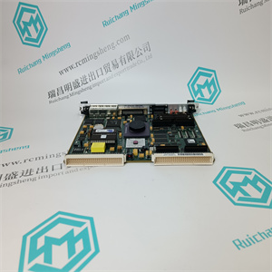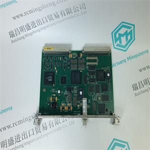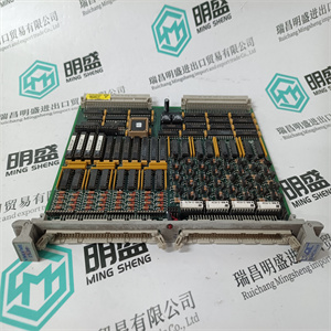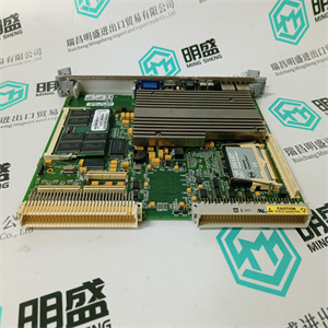

MHD093B-058-PP1-BN R911279022 应用于伺服电机 REXROTH
在测量系统的工作寿命期间,可能会发生干扰测量系统和
过程这些干扰可能以多种不同的方式出现,故障原因可能是:
很难找到。然而,性质相似的干扰可以组合在一起
通常,它们具有相同或相似的错误来源。
本章中的故障跟踪说明将帮助您快速找到并纠正most
常见故障。
6.2安全说明
跟踪故障时,请阅读并遵循1章“介绍”中给出的安全说明。
然而,如果当地法规更严格,则应优先考虑。
6.3互换性
6.4必要的设备和文件
执行故障跟踪和维修需要以下项目:
•电缆图,见附录(B、C、D、E、F或G)中安装的称重传感器类型
•服务工具
•扭矩扳手
•万用表
计量单位
张力电子装置:张力电子装置PFEA113是可互换的
具有相同类型的张力电子装置。
需要新的设置。
称重传感器:称重传感器可直接互换
具有相同类型的其他称重传感器。
零位设置PFEA113和重置“大值”
“荷载A”、“大荷载B”、“大荷载C”或
称重传感器达到以下条件后,需要“大载荷D”
已被替换。
张力电子PFEA113,用户手册
6章故障追踪
6-2 3 BSE029382R0101版本C
6.5故障追踪程序
故障症状中的故障
机械安装:机械安装中的故障通常很明显
将自身视为不稳定的零点或不正确
体贴
如果故障与工艺参数相关,例如
作为温度,或者可以与特定
操作时,故障可能来自
安装的机械部分。
称重传感器的称重传感器校准数据不变
逐步地称重传感器取决于其尺寸和类型,
可承受高达五(1)倍的额定负载
测量方向。工艺线中的事件,
如卷筒纸断裂,可能导致超载
足够大以改变称重传感器数据。取决于
过载量,可以设置为零。
(1) 阅读附录B、C、D、E、F或G中有关称重传感器类型过载能力的更多信息。
布线问题,如故障或零点不稳定
可能由电缆或接线故障引起。
靠近噪音电缆可能会造成干扰
问题。
安装不正确,如连接电缆芯
不对称或两端接地的屏蔽
而不是仅在一端,可能显示为
不稳定的零点。
如果称重传感器信号的极性不正确,
必须检查电缆。
张力电子设备:功能间歇性丧失通常是由故障引起的
在张力电子装置中。
不稳定问题很少源于紧张局势
电子学
连接到张力电子设备的设备故障
这可能会影响其操作。
张力电子PFEA113,用户手册
6.6节PFEA113中的错误和警告信息
3BSE029382R0101版本C 6-3
6.6 PFEA113中的错误和警告信息
错误是导致电子设备无法正常工作的原因。
警告可能会影响测量精度。
当出现警告或错误时,将在
操作员面板和“状态”指示从绿色变为红色。
按下时,信息将从显示屏上消失。
如果激活警告或错误消息的问题已消失
“状态”指示变为绿色。
如果错误或警告仍为“状态”ind
MHD093B-058-PP1-BN R911279022 应用于伺服电机 REXROTH
MHD093B-058-PP1-BN R911279022 应用于伺服电机 REXROTH
During the working life of your measurement system, events may occur that disturb it and your
process. These disturbances may appear in many different ways and the reason for the fault can
be difficult to find. However, disturbances similar in character can be grouped together and
usually they have the same or similar sources of error.
The fault-tracing instructions in this chapter will help you to quickly find and correct the most
common faults.
6.2 Safety Instructions
Read and follow the safety instructions given in Chapter 1 Introduction when tracing faults.
However, local statutory regulations, if stricter, are to take precedence.
6.3 Interchangeability
6.4 Necessary Equipment and Documentation
The following items are required to perform fault-tracing and repairs:
• Cable diagrams, see Appendix (B, C, D, E, F or G) for installed load cell type
• Service tools
• Torque wrench
• Multimeter
Unit Measures
Tension Electronics The tension electronics PFEA113 is interchangeable
with a tension electronics of the same type.
A new setup is required.
Load cells The load cells are directly interchangeable
with other load cells of the same type.
Zero setting PFEA113 and resetting “Maximum
Load A”, “Maximum Load B”, “Maximum Load C” or
“Maximum Load D” are required after a load cell has
been replaced.
Tension Electronics PFEA113, User Manual
Chapter 6 Fault-tracing
6-2 3BSE029382R0101 Rev C
6.5 Fault-tracing Procedure
Faults in the... Fault symptoms
Mechanical installation Faults in the mechanical installation usually manifest
themselves as an unstable zero point or incorrect
sensitivity.
If a fault is associated with a process parameter, such
as the temperature, or can be linked with a particular
operation, the fault is likely to emanate from the
mechanical part of the installation.
Load cells Calibration data for a load cell does not change
gradually. A load cell, depending on its size and type,
can withstand up to five times(1) the nominal load in
the measuring direction. An event in the process line,
such as web breakage, may cause an overloading
large enough to alter load cell data. Depending on the
amount of overload, it may be sufficient to zero set.
(1) Read more about the overload capacity for your load cell type in Appendix B, C, D, E, F or G.
Cabling Problems such as malfunctions or unstable zero point
may arise from faulty cables or wiring.
Proximity to noisy cables may cause interference
problems.
Incorrect installation, such as cable cores connected
asymmetrically or screens earthed at both ends
instead of only at one end, may show up as an
unstable zero point.
If the polarity of load cell signals is not correct,
the cabling has to be checked.
Tension Electronics Intermittent loss of a function is usually due to a fault
in the tension electronics.
Instability problems seldom originate from the tension
electronics.
Faults in devices connected to the tension electronics
may affect its operation.
Tension Electronics PFEA113, User Manual
Section 6.6 Error and Warning Messages in PFEA113
3BSE029382R0101 Rev C 6-3
6.6 Error and Warning Messages in PFEA113
An ERROR is something that causes the electronics to function incorrectly.
A WARNING is something that might affect the accuracy of the measurement.
When a warning or an error occurs, a warning or an error message is displayed on the
Operator Panel and the “Status” indication turns from green to red.
When is pressed the message disappears from the display.
If the problem that activated the warning or error message has disappeared the
“Status” indication turns to green.
If the error or warning remains the “Status” ind
MHD093B-058-PP1-BN R911279022 应用于伺服电机 REXROTH

