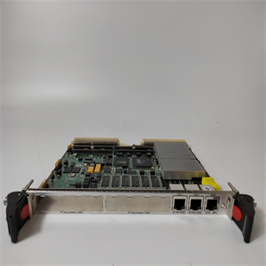
RUSB-02 3AUA0000040000 模拟量前驱动模块 ABB
e以下说明适用于典型的安装布置。允许变化,
只要符合第E.4节“安装要求”的要求。
如果需要使用管状定位销来固定称重传感器的位置,
参见图E-3中的说明。
1.清洁基础和其他安装表面。
2.将下部转接板安装到称重传感器上。
将螺钉拧紧至表E-1中规定的扭矩。
3.将称重传感器和下部适配器板安装到基础上,
但不要完全拧紧螺钉。
4.将上转接板安装到称重传感器上。
将螺钉拧紧至表E-1中规定的扭矩。
5.将轴承箱和辊安装到上适配器板上,
但不要完全拧紧螺钉。
注意安全
在此操作过程中,如果以下情况,可能会使称重传感器过载:
不要太小心,尤其是如果辊很重。临界负荷
细胞自然是PFTL 101A-0.5kN和PFTL 101-2kN。应用
倾斜安装是关键的。
6.调整称重传感器,使其相互平行并与轴向一致
辊的方向。拧紧地脚螺钉,见表E-1。
7.调整辊,使其与称重传感器的纵向成直角。
拧紧上转接板中的螺钉,见表E-1。
表E-1.称重传感器PFTL 101的拧紧力矩
替代类型的螺钉强度
班
类型
润滑尺寸
收紧
扭矩
[Nm]±5%
1.
(推荐)
合金钢螺钉
强度等级符合ISO 898/1
M12 136纳米
12.9油M16 333 Nm
M20649纳米
2.
(推荐)
合金钢螺钉
强度等级符合ISO 898/1
M12 117纳米
12.9 MoS2 M16 286纳米
M20558纳米
3.
不锈钢(A2-80)A2-80 M12 76纳米
或耐酸钢(A4-80)或蜡M16 187纳米
强度等级符合ISO 3506 A4-80 M20 364 Nm
4.
不锈钢(A2-80)A2-80油M12 65 Nm
或耐酸钢(A4-80),或M16 161纳米
强度等级根据ISO 3506 A4-80乳液M20 313 Nm
张力电子PFEA113,用户手册
第E.7.1节称重传感器电缆的布线
3BSE029382R0101版本C E-9
图E-3.钻定位销孔
E、 7.1称重传感器电缆的布线
电缆必须用夹具支撑并布线,以防止通过
缆绳
B/BE/BER 5
ial A/AE/B/BE不锈钢:
SS 2383
DIN 17440 X12CrMoS17
Werkstoffnr 1.4104
AISI 430F
AER/BER耐酸钢:
SS 2348
DIN 17440
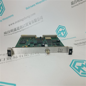
RUSB-02 3AUA0000040000 模拟量前驱动模块 ABB
RUSB-02 3AUA0000040000 模拟量前驱动模块 ABB
e instructions below apply to a typical mounting arrangement. Variations are allowed,
provided that the requirements of Section E.4, Installation Requirements are complied with.
If it is necessary to use tubular dowel pins to secure the position of the load cell,
see instructions in Figure E-3.
1. Clean the foundation and other mounting surfaces.
2. Fit the lower adapter plate to the load cell.
Tighten the screws to the torque stated in Table E-1.
3. Fit the load cell and the lower adapter plate to the foundation,
but do not fully tighten the screws.
4. Fit the upper adapter plate to the load cell.
Tighten the screws to the torque stated in Table E-1.
5. Fit the bearing housing and the roll to the upper adapter plate,
but do not fully tighten the screws.
CAUTION
During this operation it is possible to over load the load cells if the operation is
done not careful enough, especially if the roll is heavy. The most critical load
cells are naturally the PFTL 101A-0.5 kN and PFTL 101B-2 kN. Applications
with inclined mounting are most critical.
6. Adjust the load cells so that they are in parallel with each other and in line with the axial
direction of the roll. Tighten the foundation screws, see Table E-1.
7. Adjust the roll so that it is at right angles to the longitudinal direction of the load cells.
Tighten the screws in the upper adapter plate, see Table E-1.
Table E-1. Tightening Torques for Load Cell PFTL 101
Alternative Type of screws Strength
class
Type of
lubrication Dimension
Tightening
torque
[Nm] ± 5%
1
(Recommended)
Alloyed steel screws
Strength class according to ISO 898/1
M12 136 Nm
12.9 Oil M16 333 Nm
M20 649 Nm
2
(Recommended)
Alloyed steel screws
Strength class according to ISO 898/1
M12 117 Nm
12.9 MoS2 M16 286 Nm
M20 558 Nm
3
Stainless steel (A2-80) A2-80 M12 76 Nm
or acid resistant steel (A4-80), or Wax M16 187 Nm
Strength class according to ISO 3506 A4-80 M20 364 Nm
4
Stainless steel (A2-80) A2-80 Oil M12 65 Nm
or acid resistant steel (A4-80), or or M16 161 Nm
Strength class according to ISO 3506 A4-80 emulsion M20 313 Nm
Tension Electronics PFEA113, User Manual
Section E.7.1 Routing the Load Cell Cable
3BSE029382R0101 Rev C E-9
Figure E-3. Drilling Dowel Pin Holes
E.7.1 Routing the Load Cell Cable
The cable must be supported with clamps and routed to prevent force shunting through the
cable.
B/BE/BER 5
ial A/AE/B/BE Stainless steel:
SS 2383
DIN 17440 X12CrMoS17
Werkstoffnr 1.4104
AISI 430F
AER/BER Acid resistant steel:
SS 2348
DIN 17440
RUSB-02 3AUA0000040000 模拟量前驱动模块 ABB