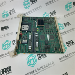
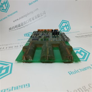
MCD0300256001 驱动器用于控制传输速度 Kollmorgen MCD0300256001 驱动器用于控制传输速度 Kollmorgen大浪涌电流。✶0.8A
浪涌电流持续时间(大)0.5ms
信号开启延迟,大
信号关闭延迟,大
大35毫秒
大45毫秒
✶ 交流输入设备必须与SLC 500输入电路浪涌电流兼容。限流电阻器可用于限制涌入电流。然而,ac的运行特性
输入电路受到影响。
交流输出模块
规格
产出数量
每公分点数
电压类别
工作电压范围
5V时的底板电流(mA)
24V时的底板电流(mA)
电压降,接通状态输出,大。
负载电流,小。
漏电流,截止状态输出,大
每点浪涌电流(大值)‡
信号接通延迟,大(电阻负载)§
信号关闭延迟,大(电阻负载)§
✶ 1746-OAP12模块具有带保险丝的普通和熔断保险丝LED指示灯。
为了限制固态输出漏电流的影响,可以将负载电阻器与负载并联。对于120V交流操作,使用15KΩ,2W电阻器。对于240V ac
操作时,使用15KΩ、5W电阻器。
‡重复性为30°C(86°F)时每1s一次。重复性在60°C(140°F)时每2 s进行一次。
§三端双向可控硅开关元件输出在交流线路周期的任何点接通,并在交流线路零交叉点断开。
♣ 推荐浪涌抑制:对于切换120V交流感应负载时的三端双向可控硅开关输出,使用型号为V220MA2A的Harris金属氧化物变阻器。请参阅SLC 500模块
有关浪涌抑制的更多信息,请参阅1747-UM011号出版物《硬件风格用户手册》。
➤ 浪涌电流=35 A,每个公共电源持续10 ms。
出版物1747-SG001D-EN-P-2009年1月
13
继电器输出模块
规格
产出数量
每公分点数
电压类别
工作电压范围
5V时的底板电流(mA)
24V时的底板电流(mA)
负载电流,小。
信号接通延迟,大(电阻负载)
大信号关闭延迟(电阻负载)
每点连续电流‡
每个模块的连续电流
1746-OW4
4.
4.
交流/直流隔离
漏电流,关闭状态输出,大0 mA
✶ 限制每个模块的连续电流,使模块功率不超过1440 VA。
经CSA认证的1类2类危险场所。
‡推荐浪涌抑制:对于继电器输出,请参阅SLC 500模块化硬件风格用户手册,出版物1747-UM011。连接外部浪涌抑制器
电感负载将延长SLC继电器触点的寿命。
继电器触点额定值
✶ 跨外部负载连接浪涌抑制器可延长SLC 500继电器触点的寿命。有关切换交流感应负载时的推荐浪涌抑制,请咨询SLC
500模块化硬件风格用户手册,出版物1746-UM011。开关24V直流感应负载的推荐浪涌抑制是跨负载的1N4004二极管反向接线。
对于直流电压应用,继电器触点的接通/断开额定电流可通过将28 VA除以所施加的直流电压来确定。例如,28 VA/48V直流电=0.58 A直流电
对于小于14V的电压应用,继电器触点的接通/断开额定值不得超过2A。
-必须限制每个模块的连续电流,以便模块功率不超过1440 VA。
出版物1747-SG001D-EN-P-2009年1月
14
I/O模块组合
规格
24V直流电(输入)
100/120V交流(继电器触点输出)
10…30V直流电(输入)
47…63 Hz/5…125V直流时的5…265V交流
(产出)
90毫安80毫安
70毫安60毫安
参见13页的1746-OW16继电器触点额定值。
8A8A
工作电压范围
5V时的底板电流(mA)
24V时的底板电流(mA)
每点连续电流
每个模块的连续电流
85…132V ac,47…63 Hz(输入)
47…63 Hz时的5…265V ac/5…125V dc(输出)
30毫安至60毫安
25毫安45毫安
参见13页的1746-OW4继电器触点额定值。
4A8A
1746-SIM输入
模拟器
1746-SIM输入模拟器设计用于16信道24V直流吸收和
采购带有可拆卸接线板的模块,包括1746-IB16、1746-ITB16,
1746-IV16、1746-ITV16和1746-IN16模块。输入模拟器提供16
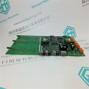
用于模拟到SLC 500的输入的开关。 MCD0300256001 驱动器用于控制传输速度 Kollmorgen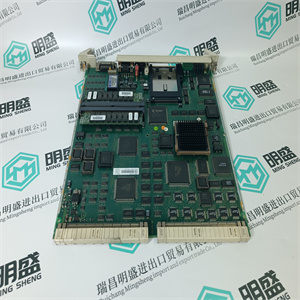 MCD0300256001 驱动器用于控制传输速度 Kollmorgen MCD0300256001 驱动器用于控制传输速度 Kollmorgen
Inrush Current, Max.✶0.8 A
Inrush Current Time Duration (max.) 0.5 ms
Signal On Delay, Max
Signal Off Delay, Max
35 ms max
45 ms max
✶ An ac input device must be compatible with SLC 500 input circuit inrush current. A current limiting resistor can be used to limit inrush current. However, the operating characteristics of the ac
input circuit are affected.
AC Output Modules
Specifications
Number of Outputs
Points Per Common
Voltage Category
Operating Voltage Range
Backplane Current (mA) at 5V
Backplane Current (mA) at 24V
Voltage Drop, On-State Output, Max.
Load Current, Min.
Leakage Current, Off-State Output, Max
Surge Current per Point (max.)‡
Signal On Delay, Max (resistive load)§
Signal Off Delay, Max (resistive load)§
✶ The 1746-OAP12 module features a fused common and blown fuse LED indicator.
To limit the effects of leakage current through solid-state oututs, a loading resistor can be connected in parallel with your load. For 120V ac operation, use a 15 kΩ, 2 W resistor. For 240V ac
operation, use a 15 kΩ, 5 W resistor.
‡ Repeatability is once every 1 s @ 30 °C (86 °F). Repeatability is once every 2 s @ 60 °C (140 °F).
§ Triac outputs turn on at any point in the ac line cycle and turn off at ac line zero cross.
♣ Recommended surge suppression: For triac outputs when switching 120V ac inductive loads, use Harris Metal-oxide Varistor, model number V220MA2A. Refer to the SLC 500 Modular
Hardware Style User Manual, publication 1747-UM011 for more information on surge suppression.
➤ Surge current = 35 A per common for 10 ms.
Publication 1747-SG001D-EN-P — January 2009
13
Relay Output Modules
Specifications
Number of Outputs
Points Per Common
Voltage Category
Operating Voltage Range
Backplane Current (mA) at 5V
Backplane Current (mA) at 24V
Load Current, Min.
Signal On Delay, Max (resistive load)
Signal Off Delay, Max (resistive load)
Continuous Current per Point‡
Continuous Current per Module
1746-OW4
4
4
ac/dcsolated
Leakage Current, Off-State Output, Max 0 mA
✶ Limit continuous current per module so that module power does not exceed 1440 VA.
Certified for Class 1 Div 2 Hazardous Locations by CSA.
‡ Recommended surge suppression: for relay outputs, refer to SLC 500 Modular Hardware Style User Manual, publication 1747-UM011. Connecting surge suppressors across your external
inductive load will extend the life of SLC relay contacts.
Relay Contact Ratings
✶ Connecting surge suppressors across your external load extends the life of SLC 500 relay contacts. For recommended surge suppression when switching ac inductive loads, consult the SLC
500 Modular Hardware Style User Manual, publication 1746-UM011. Recommended surge suppression for switching 24V dc inductive loads is 1N4004 diode reverse wired across the load.
For dc voltage applications, the make/break ampere rating for relay contacts can be determined by dividing the 28 VA by the applied dc voltage. For example, 28 VA/48V dc = 0.58 A for dc
voltage applications less than 14V, the make/break ratings for relay contacts cannot exceed 2 A.
‡ The continuous current per module must be limited so the module power does not exceed 1440 VA.
Publication 1747-SG001D-EN-P — January 2009
14
Combination I/O Modules
Specifications
24V dc (Inputs)
100/120V ac (Relay Contact Outputs)
10…30V dc (Inputs)
5…265V ac @ 47…63 Hz / 5…125V dc
(Outputs)
90 mA80 mA
70 mA60 mA
See Relay Contact Ratings for 1746-OW16 on page 13.
8A8A
Operating Voltage Range
Backplane Current (mA) at 5V
Backplane Current (mA) at 24V
Continuous Current per Point
Continuous Current per Module
85…132V ac @ 47…63 Hz (Inputs)
5…265V ac @ 47…63 Hz / 5…125V dc (Outputs)
30 mA60 mA
25 mA45 mA
See Relay Contact Ratings for 1746-OW4 on page 13.
4A8A
1746-SIM Input
Simulator
The 1746-SIM Input Simulator is designed for use on 16-channel 24V dc sinking and
sourcing modules with removable terminal blocks, including 1746-IB16, 1746-ITB16,
1746-IV16, 1746-ITV16, and 1746-IN16 modules. The input simulator provides 16
switches for simulating inputs to the SLC 500.
| | | | |