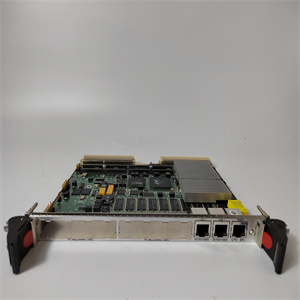
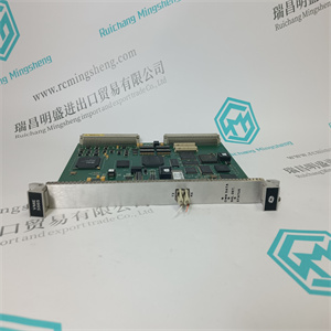
IDPG 940128102 PLC通讯接口卡
消息传递。IED满足GOOSE跳闸性能要求
IEC 61850标准定义的配电变电站应用。这个
IED可以在车站总线上同时向五个不同的客户端报告事件。
IED可以同时支持五个客户端。如果PCM600保留一个客户端
连接,仅剩下四个客户端连接,例如IEC 61850和
Modbus。
除前端口连接器外,所有通信连接器均放置在
集成可选通信模块。IED可以通过RJ-45连接器(100Base TX)或fibreoptic LC连接器(100Base FX)连接到基于以太网的通信系统。可选的串行接口可用于:
RS-232/RS-485通信。
对于冗余环路拓扑的正确操作,外部
网络中的交换机支持RSTP协议,并且在
开关。否则,连接回路拓扑可能会导致
网络IED本身不支持链路中断检测或RSTP。戒指
恢复过程基于MAC地址和链路上/链路下的老化
事件可能导致通信暂时中断。为了更好地执行
对于自愈回路,建议距离
615 IED环路被分配为根交换机(网桥优先级=0)和网桥
优先级向IED回路增加。IED回路的末端链路可以是:
连接到同一外部开关或两个相邻的外部开关。自愈以太网环需要至少两个以太网的通信模块
所有IED的接口。
第2节1MRS756378 K
参考文献615概述
22参考文献615
应用手册
16384
32 16 0 0
0
16384
128 48 32 16
40960 32768
160 144
128 112
80 96 112 176
36864 45056
桥梁优先
32768
64 48
港口优先权
RE_615 RE_
RE_615 RE_
GUID-283597AF-9F38-4FC7-B87A-73BFDA272D0F V1 EN
图5:自愈以太网环解决方案
以太网环网解决方案支持多达30个
615系列IED。如果要连接30多个IED,则
建议将网络拆分为多个环,不使用
每个环有30多个简易爆炸装置。
1MRS756378 K第2节
参考文献615概述
参考文献615 23
应用手册
24
第3节,参考615:标准配置
3.1标准配置
REF615有九种可选的标准配置。标准
信号配置可通过图形信号矩阵或
保护和控制IED管理器的图形应用功能
此外,PCM600的应用程序配置功能支持
使用各种逻辑元素创建多层逻辑函数,包括
定时器和触发器。通过将保护功能与逻辑功能相结合
块,IED配置可适用于用户特定应用
要求。
表8:标准配置
描述标准配置。
无方向过电流和方向接地故障保护和CB控制A
无方向过电流和方向接地故障保护、断路器状态监测、断路器
控制和可选I/O模块控制两个网络对象B
无方向过电流和无方向接地故障保护和CB控制C
无方向过电流和无方向接地故障保护、断路器状态监测、断路器
控制和可选I/O模块控制两个网络对象D
基于相电压的无方向过电流和方向接地故障保护
测量、断路器状态监测和断路器控制E
基于相电压的定向过电流和定向接地故障保护
测量、欠压和过压保护、断路器状态监测和断路器控制
方向过电流和方向接地故障保护、相电压保护和
测量功能、断路器状态监测、断路器控制和传感器输入G
无方向过电流和无方向接地故障保护、相电压和频率
基于保护和测量功能、同步检查、CB状态监测和CB控制H
基于相电压和频率的定向过电流和定向接地故障保护
保护和测量功能、同步检查、断路器状态监测和断路器控制J IDPG 940128102 PLC通讯接口卡
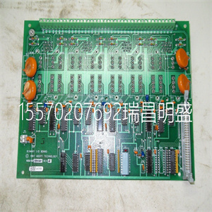 IDPG 940128102 PLC通讯接口卡
messaging. The IED meets the GOOSE performance requirements for tripping
applications in distribution substations, as defined by the IEC 61850 standard. The
IED can simultaneously report events to five different clients on the station bus.
The IED can support five simultaneous clients. If PCM600 reserves one client
connection, only four client connections are left, for example, for IEC 61850 and
Modbus.
All communication connectors, except for the front port connector, are placed on
integrated optional communication modules. The IED can be connected to Ethernetbased communication systems via the RJ-45 connector (100Base-TX) or the fibreoptic LC connector (100Base-FX). An optional serial interface is available for
RS-232/RS-485 communication.
For the correct operation of redundant loop topology, it is essential that the external
switches in the network support the RSTP protocol and that it is enabled in the
switches. Otherwise, connecting the loop topology can cause problems to the
network. The IED itself does not support link-down detection or RSTP. The ring
recovery process is based on the aging of MAC addresses and link-up/link-down
events can cause temporary breaks in communication. For better performance of
the self-healing loop, it is recommended that the external switch furthest from the
615 IED loop is assigned as the root switch (bridge priority = 0) and the bridge
priority increases towards the IED loop. The end links of the IED loop can be
attached to the same external switch or to two adjacent external switches. Selfhealing Ethernet ring requires a communication module with at least two Ethernet
interfaces for all IEDs.
Section 2 1MRS756378 K
REF615 overview
22 REF615
Application Manual
16384
32 16 0 0
0
16384
128 48 32 16
40960 32768
160 144
128 112
80 96 112 176
36864 45056
Bridge priority
32768
64 48
Port priority
RE_615 RE_615 RE_615 RE_615
RE_615 RE_615 RE_615 RE_615
GUID-283597AF-9F38-4FC7-B87A-73BFDA272D0F V1 EN
Figure 5: Self-healing Ethernet ring solution
The Ethernet ring solution supports the connection of up to thirty
615 series IEDs. If more than 30 IEDs are to be connected, it is
recommended that the network is split into several rings with no
more than 30 IEDs per ring.
1MRS756378 K Section 2
REF615 overview
REF615 23
Application Manual
24
Section 3 REF615 standard configurations
3.1 Standard configurations
REF615 is available in nine alternative standard configurations. The standard
signal configuration can be altered by means of the graphical signal matrix or the
graphical application functionality of the Protection and Control IED Manager
PCM600. Further, the application configuration functionality of PCM600 supports
the creation of multi-layer logic functions using various logical elements, including
timers and flip-flops. By combining protection functions with logic function
blocks, the IED configuration can be adapted to user-specific application
requirements.
Table 8: Standard configurations
Description Std. conf.
Non-directional overcurrent and directional earth-fault protection and CB control A
Non-directional overcurrent and directional earth-fault protection, CB condition monitoring, CB
control and with the optional I/O module control of two network objects B
Non-directional overcurrent and non-directional earth-fault protection and CB control C
Non-directional overcurrent and non-directional earth-fault protection, CB condition monitoring, CB
control and with the optional I/O module control of two network objects D
Non-directional overcurrent and directional earth-fault protection with phase-voltage based
measurements, CB condition monitoring and CB control E
Directional overcurrent and directional earth-fault protection with phase-voltage based
measurements, undervoltage and overvoltage protection, CB condition monitoring and CB control F
Directional overcurrent and directional earth-fault protection, phase-voltage based protection and
measurement functions, CB condition monitoring, CB control and sensor inputs G
Non-directional overcurrent and non-directional earth-fault protection, phase-voltage and frequency
based protection and measurement functions, synchro-check , CB condition monitoring and CB control H
Directional overcurrent and directional earth-fault protection, phase-voltage and frequency based
protection and measurement functions, synchro check, CB condition monitoring and CB control J
| | |