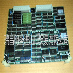
ABB 40PB3204A 工控模块卡件PLC/DCS备件模块 包邮全系列供应
功能图描述了默认输入、输出、报警LED和功能到功能连接。可以使用查看和更改默认连接
如有必要,根据应用要求提供PCM600。
模拟通道具有指向不同功能块的固定连接
在IED的标准配置中。这条规则的例外是12
用于干扰记录器功能的模拟通道。这些渠道是:
可自由选择,是干扰记录器参数设置的一部分。
模拟信道分配给不同的功能。公共信号
用3I表示三相电流。标有Io的信号
表示通过铁芯平衡电流互感器测量的剩余电流。
标有Uo的信号表示通过开放增量测量的剩余电压
连接到电压互感器。
双(越野)接地故障的EFHPTOC保护功能块
使用源自测量相电流的计算剩余电流。
3.8.3.1保护功能图
功能图详细描述了IED的保护功能,以及
想象工厂设置的默认连接。
提供四个过电流级,用于过电流和短路保护。
瞬时级(PHIPTOC1)可以通过给二进制通电来阻止
输入1(X120:1-2)。两个负序过电流级(NSPTOC1和
NSPTOC2)用于相位不平衡保护。涌流检测
块的(INRPHAR1)输出BLK2H启用功能块或
将任何所述保护功能块的有效设置相乘。
提供四个过电流级,用于过电流和短路保护。
瞬时级(PHIPTOC1)可以通过给二进制通电来阻止
输入1(X120:1-2)。两个负序过电流级(NSPTOC1和
NSPTOC2)用于相位不平衡保护。涌流检测
块的(INRPHAR1)输出BLK2H启用功能块或
将任何所述保护功能块的有效设置相乘。
1MRS756378 K第3节
REF615标准配置
参考文献615:97
应用手册
GUID-37D627C4-6097-4322-BACC-161CC6039EC5 V2 EN
图46:过电流保护
所有操作信号均连接至主跳闸和报警LED。LED 1
用于过电流,LED 4用于负序过电流保护
操作指示。LED 4也用于相位不连续保护操作
指示
从过电流第二高阶段开始的上游阻塞
(PHHPTOC2)连接到输出SO1(X110:14-16)。使用此输出
用于向相关过电流保护级发送闭锁信号
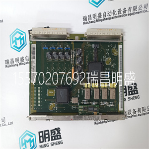
在进料舱的简易爆炸装置 ABB 40PB3204A 工控模块卡件PLC/DCS备件模块 包邮全系列供应
 ABB 40PB3204A 工控模块卡件PLC/DCS备件模块 包邮全系列供应
he functional diagrams describe the default input, output, alarm LED and functionto-function connections. The default connections can be viewed and changed with
PCM600 according to the application requirements, if necessary.
The analog channels have fixed connections towards the different function blocks
inside the IED’s standard configuration. Exceptions from this rule are the 12
analog channels available for the disturbance recorder function. These channels are
freely selectable and a part of the disturbance recorder’s parameter settings.
The analog channels are assigned to different functions. The common signal
marked with 3I represents the three phase currents. The signal marked with Io
represents the measured residual current via a core balance current transformer.
The signal marked with Uo represents the measured residual voltage via open delta
connected voltage transformers.
The EFHPTOC protection function block for double (cross-country) earth-faults
uses the calculated residual current originating from the measured phase currents.
3.8.3.1 Functional diagrams for protection
The functional diagrams describe the IED’s protection functionality in detail and
picture the factory set default connections.
Four overcurrent stages are offered for overcurrent and short-circuit protection.
The instantaneous stage (PHIPTOC1) can be blocked by energizing the binary
input 1 (X120:1-2). Two negative sequence overcurrent stages (NSPTOC1 and
NSPTOC2) are offered for phase unbalance protection. The inrush detection
block’s (INRPHAR1) output BLK2H enables either blocking the function or
multiplying the active settings for any of the described protection function blocks.
1MRS756378 K Section 3
REF615 standard configurations
REF615 97
Application Manual
GUID-37D627C4-6097-4322-BACC-161CC6039EC5 V2 EN
Figure 46: Overcurrent protection
All operate signals are connected to the Master Trip and to the alarm LEDs. LED 1
is used for overcurrent and LED 4 for negative-sequence overcurrent protection
operate indication. LED 4 is also used for phase discontinuity protection operate
indication.
The upstream blocking from the start of the overcurrent second high stage
(PHHPTOC2) is connected to the output SO1 (X110:14-16). This output is used
for sending a blocking signal to the relevant overcurrent protection stage of the
IED at the infeeding bay | ABB 40PB3204A 工控模块卡件PLC/DCS备件模块 包邮全系列供应 | | | |