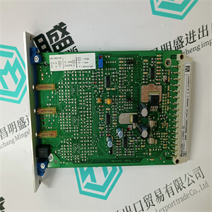
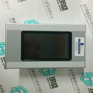
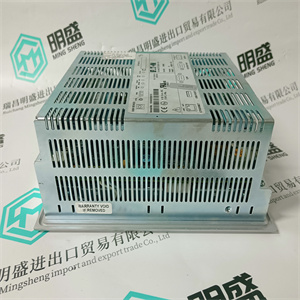
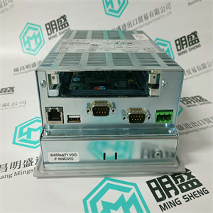
5AP1130.156C-000 安装在专用DCS系统控制触摸屏 B&R
5AP1130.156C-000 安装在专用DCS系统控制触摸屏 B&R
要将PM891装置安装在DIN导轨上,请使用刀片螺丝刀将其牢固地安装到
需要装置锁紧螺钉(1 mm槽)。有关单元锁定的详细信息,请参阅
螺钉,参见第77页图20。
将PM891装置安装在DIN导轨上:
1.将锁定装置旋转至打开位置(1),将上唇钩在
装置后部牢固地位于DIN导轨的上边缘,并轻轻地卡入
装置完全进入安装位置。
2.将锁定装置旋转至滑动位置(2),沿
DIN导轨至所需安装位置,并使用连接器插头和
插座轻轻地将其连接到相邻的装置底板上。
图19.AC 800M控制器(PM891除外)-侧视图
为防止损坏引脚,确保基板插头和插座
单元互连时完全对齐。不要施加过大的力。
第二节预制铝型材安装
3BSE036351-600 A 77
3.互连完成后,顺时针旋转锁定装置
锁定位置(3)。PM891装置现在完全锁定在
定位并与DIN导轨有良好的接地连接。
必须将锁定装置置于锁定位置,以便:
避免振动和/或间歇性接地可能导致的问题。
图20.PM891的装置锁定
图21.安装在DIN导轨上的其他装置的PM891
1.打开2.滑动3.锁定
预制铝型材第2节安装
78 3BSE036351-600 A
拆除带有底板的处理器单元
使用以下步骤拆卸装置,包括底板:
1.关闭或断开控制器单元的电源。
2.从适当的装置底板上拆下任何可拆卸电缆。
图22.PM891-侧视图
拆除AC 800M装置之前,必须断开电源
他们从喧闹的轨道上!
不允许在通电和运行状态下操纵CEX总线底板
系统在更换或移除基板之前,该基板上的所有CEX模块
必须删除段。
第二节预制铝型材安装
3BSE036351-600 A 79
3.将锁定装置旋转到单元基板上的滑动位置(2),
参见第75页图17。
4.轻轻地从侧面松开装置/底板,以释放
正在拆除装置底板。
5.逆时针转动锁紧装置至打开位置(1),并松开
装置底板在底座处向外和向上。提起装置,将其从
DIN导轨。AC 800M装置必须与电源断开连接
然后将其从DIN导轨上拆下。
为了提供足够的进入和拆卸空间,请注意,滑块
必须在与装置相邻的装置基板上执行顺序,即:
将被移除。
通过轻轻撬动,装置底板可以轻松地彼此断开
用一字螺丝刀将它们分开(参见第80页图23)。
预制铝型材第2节安装
80 3BSE036351-600 A
图23.分离底板
F
R
接收/发送
实时战略
F
R
Rx1
Tx1
Rx2
Tx2
CI853
COM1和COM2
F
R
P
初始化
B
PM860
CN1 CN2 COM3 COM4
CI851
第二节预制铝型材安装
3BSE036351-600 A 81
装置至基板阿尔法密码锁
底板具有预设的阿尔法码锁定装置。该锁定装置防止:
在基板上安装不兼容类型的装置,如果Alpha代码
不匹配。所有相同的装置类型都具有相同的出厂预设值,两个字母α
交付前安装的代码。
以下装置类型安装了两部分预设阿尔法码锁定装置
(见第81页表4)。
表4.工厂预设阿尔法代码
装置键位置1键位置2
CI853 RS-232C接口A C
CI854/CI854A/CI854B
PROFIBUS DP接口
A D
CI855以太网接口
MasterBus 300
A、E
CI856 S100接口B A
CI857 INSUM接口B B B
CI858驱动总线接口B C
CI860基金会现场总线
高速以太网
(FF HSE)接口。
B、E
CI862 TRIO/Genius接口(无阿尔法锁定)(无阿尔法锁)
CI865 Satt输入/输出C F
CI867 Modbus TCP接口D(1)B(1)
CI868 IEC 61850接口D(1)B(1)
CI869 AF 100接口D C
CI872 MOD5接口D E
CI871 PROFINET IO接口D(1)B(1)
预制铝型材第2节安装
82 3BSE036351-600 A
有关预设Alpha代码的更多详细信息,请参阅相关装置文件。
参见第83页的图24,了解阿尔法码锁布置的更多细节。
机械钥匙是预设的,不得更改。这防止了
可拆卸接口放置在错误类型的底板上。
CI873以太网/IP设备网
界面
D(1)B(1)
BC810 CEX总线
互连单元
答
BC820 CEX总线
互连单元
EA
SM810 C B
SM811 D D
SM812 D D
(1) 关键位置对于CI867、CI868、CI871和CI873是通用的。因此必须谨慎
进行现场更换。确保插入正确的CI,特别是在热插入时。
确保底板和装置为m 5AP1130.156C-000 安装在专用DCS系统控制触摸屏 B&R
 5AP1130.156C-000 安装在专用DCS系统控制触摸屏 B&R
To mount the PM891 unit on the DIN-rail, a blade screwdriver that fits securely into
the unit locking screw (1 mm slot) is required. For details about the unit locking
screw, see Figure 20 on page 77.
To mount the PM891 unit on the DIN-rail:
1. Rotate the locking device to the OPEN position (1), hook the upper lip at the
rear of the unit securely over the upper edge of the DIN-rail, and gently snap
the unit fully into the mounting position.
2. Rotate the locking device to the SLIDE position (2), slide the unit along the
DIN-rail to the desired mounting position, and using the connector plugs and
sockets gently attach it to the adjacent unit baseplate.
Figure 19. AC 800M Controller (except PM891) – Side View
To prevent damage to the pins, ensure that the baseplate plugs and sockets are
fully aligned as the units interconnect. Do not apply excessive force.
Section 2 Installation Prefabricated aluminum profile
3BSE036351-600 A 77
3. When the interconnection is complete, rotate the locking device clockwise to
the LOCKED position (3). The PM891 unit is now fully locked into the
position and has a good ground connection to the DIN-rail.
It is essential that the locking device be placed in the LOCKED position to
avoid possible problems caused by vibration and/or intermittent grounding.
Figure 20. Unit locking for PM891
Figure 21. PM891 with other units mounted on DIN-rail
1. OPEN 2. SLIDE 3. LOCKED
Prefabricated aluminum profile Section 2 Installation
78 3BSE036351-600 A
Removing Processor Units Complete with Baseplates
Use the following procedure to remove a unit, complete with baseplate:
1. Switch off or disconnect the power supply to the controller units.
2. Remove any detachable cables from the appropriate unit baseplate.
Figure 22. PM891 - Side view
AC 800M units must be disconnected from the power source before removing
them from a DIN-rail!
It is not allowed to manipulate CEX bus baseplates in a powered and running
system. Before changing or removing a baseplate, all CEX modules on that
segment must be removed.
Section 2 Installation Prefabricated aluminum profile
3BSE036351-600 A 79
3. Rotate the locking device to the SLIDE position (2) on the unit baseplate,
see Figure 17 on page 75.
4. Gently ease the unit/baseplates sideways in order to release the contacts of the
unit baseplate being removed.
5. Turn the locking device anti-clockwise to the OPEN position (1) and ease the
unit baseplate outward and upward at the base. Lift the unit to remove it from
the DIN-rail. The AC 800M units must be disconnected from the power source
before removing them from the DIN-rail.
In order to provide adequate access and removal space, note that the SLIDE
sequence must be carried out on the unit baseplates adjacent to the unit that is
to be removed.
The unit baseplates are easily disconnected from each other by gently prying
them apart with a blade screwdriver (see Figure 23 on page 80).
Prefabricated aluminum profile Section 2 Installation
80 3BSE036351-600 A
Figure 23. Separating the Baseplates
F
R
Rx/Tx
RTS
F
R
Rx1
Tx1
Rx2
Tx2
CI853
COM1 COM2
F
R
P
INIT
B
PM860
CN1 CN2 COM3 COM4
CI851
Section 2 Installation Prefabricated aluminum profile
3BSE036351-600 A 81
Unit to Baseplate Alpha Code Lock
Baseplates have a pre-set Alpha code locking device. This locking device prevents
the installation of an incompatible type of unit onto the base plate if the Alpha codes
do not match. All identical unit types have the same factory pre-set, two-letter Alpha
code installed prior to delivery.
The following unit types have two-part, pre-set Alpha code locking devices installed
(see Table 4 on page 81).
Table 4. Factory Pre-set Alpha Codes
Unit Key Position 1 Key Position 2
CI853 RS-232C Interface A C
CI854/CI854A/CI854B
PROFIBUS DP Interface
A D
CI855 Ethernet interface for
MasterBus 300
A E
CI856 S100 interface B A
CI857 INSUM Interface B B
CI858 DriveBus Interface B C
CI860 FOUNDATION Fieldbus
High Speed Ethernet
(FF HSE) Interface.
B E
CI862 TRIO/Genius Interface (no Alpha lock) (no Alpha lock)
CI865 Satt I/O C F
CI867 Modbus TCP Interface D(1) B(1)
CI868 IEC 61850 Interface D(1) B(1)
CI869 AF 100 Interface D C
CI872 MOD5 Interface D E
CI871 PROFINET IO Interface D(1) B(1)
Prefabricated aluminum profile Section 2 Installation
82 3BSE036351-600 A
For further details on pre-set Alpha codes, refer to the relevant unit documentation.
See Figure 24 on page 83 for further details of the Alpha code lock arrangement.
The mechanical keys are delivered pre-set and must not be altered. This prevents the
removable interface being placed on the wrong type of baseplate.
CI873 EtherNet/IP DeviceNet
Interface
D(1) B(1)
BC810 CEX-Bus
Interconnection Unit
C A
BC820 CEX-Bus
Interconnection Unit
E A
SM810 C B
SM811 D D
SM812 D D
(1) The key positions are common to CI867, CI868, CI871 and CI873. Hence caution must be
exercised in field replacement. Ensure that correct CI is inserted, especially in hot insert.
Ensure that the baseplate and the unit to be mounted have compatible Alpha codes.
Otherwise it may result in equipment damage. Any difficulty in installing a unit on a
particular baseplate indicates a difference in Alpha Code lock.
Do not manipulate the locking device. ABB will take no responsibility for
errors caused by manipulating locking devices. | 5AP1130.156C-000 安装在专用DCS系统控制触摸屏 B&R | | | | |