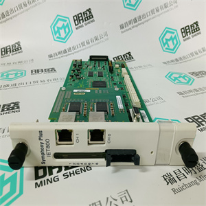
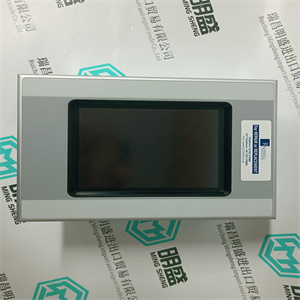
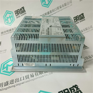
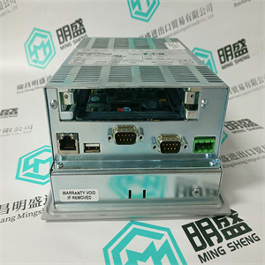
FIREYE 控制紫外自检火焰扫描器 45UV5-1000
电池单元。按照安装SB822中的说明进行安装
152页的可充电外部电池单元。
通信端口-CN1和CN2
控制网络连接到一个或两个RJ45连接器(CN1和CN2)
取决于网络选项(单个或冗余)。
使用IEEE802.3(以太网)的RJ45连接器连接到5类
屏蔽双绞线(STP 5级)。
光学模块总线的连接与处理器单元的连接相同
对于S800 I/O中的FCI(参见168页图59)
5级或更高,电缆10/100BaseT/TX大100米(110码)。ABB建议:
在工业环境中使用光纤,例如62.5/125
100BaseFX,大距离1500米(1600码)。
表8.TP830 CN1和CN2连接(RJ45连接器)
引脚名称方向描述
1 TD+输出传输数据(plus)
2 TD-输出传输数据(减)
接收数据中的3+条(加号)
4–5–未使用
6位-接收数据中(减)
7–8–未使用
外壳屏蔽-屏蔽
2节安装:在单个配置中安装PM891
3BSE036351-600 A 95
COM4端口
COM4端口是一个RS-232C端口,光隔离,没有调制解调器信号。
当直接连接到控制器时,将控件生成器连接到此端口,
或者,当不需要时,无需通过
控制网络。
表9.PM891 COM4连接(RJ45连接器)
引脚名称方向描述
1–未使用
2–未使用
3 TD输出传输数据
4.0 V–信号接地
5.0 V–信号接地
接收数据中的6位
7–未使用
8–未使用
外壳屏蔽-屏蔽
在冗余配置中安装PM85x/PM86x/TP830处理器单元2节
96 3BSE036351-600 A
在中安装PM85x/PM86x/TP830处理器单元
冗余配置
冗余配置2
PM858/PM861/PM862/PM864/PM865/PM866/PM867单元安装在两个
分离DIN导轨。如果有足够的空间,可将装置安装到
相同的DIN导轨
使用以下步骤沿DIN导轨安装处理器单元:
1.安装处理器单元。
2.将通信接口安装在CEX总线左侧
处理器单元。如果使用BC810/BC820,则段的配置
应当考虑。如果不使用BC810/BC820,接口可以
以任何优选的方式在两个CPU之间划分。
3.轻轻地将单元压在一起,确保CEX总线正确
通过基板上的连接器连接。
4.如果使用BC810,将TK851电缆连接到两个BC810(图31
106页)。如果使用BC820,将TK857电缆连接到两个BC820
(114页图37)。如果未使用BC810/BC820,则安装CEX总线
延伸电缆TK850至远离处理器单元的单元,
如果没有安装单元,则直接连接到处理器单元上的CEX总线。这个
CEX总线扩展电缆必须连接到两个CPU,无论是否:
还有任何其他CEX总线单元(99页图29)。
本主题不适用于冗余PM891装置的安装
配置请参阅以冗余方式安装PM891处理器单元
100页的配置。
注意,在冗余CPU配置中,COM3和电气模块总线
底板上不能使用。
2节安装:以冗余方式安装PM85x/PM86x/TP830处理器单元
3BSE036351-600 A 97
5.如果使用BC810,将RCU链路电缆TK851连接到两个CPU。注意
在冗余CPU配置中,COM3和
底板不能使用。如果使用BC820,则将TK857连接到每个
CPU,它是BC820。
6.底板电缆连接:
a、 将电源引线连接到CPU和电源监控信号
从SS8xx到螺钉端子SA和SB(参见89页图28)。
b、 将控制网络电缆连接至CN1(单总线连接),或
CN1+CN2(冗余总线连接)。控制网络是
连接到两个CPU。
c、 使用主电源的电缆TK212将控制生成器连接到COM4
CPU(如果需要更改IP地址等)。否则,连接
控制网络的控制生成器。
7.将光学模块总线连接到处理器单元上的光学触点
(参见36页图2和140页图45)。关于
S800 I/O中提供了光缆选择和电缆长度
文档
请注意,RCU链路电缆TK851或TK857必须使用,不能使用
用类似的电缆代替。使用其他电缆将禁用的标识
CB和操作员站中的CPU。在单一配置中运行时
RCU链路电缆TK851可临时用于执行以下功能:
终端插头。
如果使用BC810 us,则连接到RCU链路电缆连接器的CPU标记为
“上限”将在控件生成器和运算符中定义为“上限”
火车站标记与CPU的物理位置无关。
任何CPU都可以成为主CPU。对于 FIREYE 控制紫外自检火焰扫描器 45UV5-1000
FIREYE 控制紫外自检火焰扫描器 45UV5-1000
battery unit. Install it according to the instructions in Installing the SB822
Rechargeable External Battery Unit on page 152.
Communication Ports - CN1 and CN2
The control network connects to one or two RJ45 connectors (CN1 and CN2)
depending on network option (single or redundant).
Use an RJ45 connector for IEEE802.3 (Ethernet) for connecting to a category 5
Shielded Twisted Pair cable (STP class 5).
The connection to the optical ModuleBus is identical to that for the processor unit
and for the FCI in S800 I/O (see Figure 59 on page 168.)
Class 5, or higher, cable 10/100BaseT/TX max 100 m (110 yd). ABB recommends
the use of optical fiber in an industrial environment, for example 62.5/125
100BaseFX, max. distance 1500 m (1600 yd).
Table 8. TP830 CN1 and CN2 Connections (RJ45 connectors)
Pin Designation Direction Description
1 TD+ Out Transmit Data (plus)
2 TD- Out Transmit Data (minus)
3 RD+ In Receive Data (plus)
4–5 – – Not used
6 RD- In Receive Data (minus)
7–8 – – Not used
Housing Shield – Shield
Section 2 Installation Installing PM891 in Single Configuration
3BSE036351-600 A 95
COM4 Port
The COM4 port is an RS-232C port, opto-isolated and without modem signals.
Connect the Control Builder to this port when connecting directly to the controller,
or, when not required, without the need use the remote tool connection through the
Control Network.
Table 9. PM891 COM4 Connections (RJ45 connector)
Pin Designation Direction Description
1 – – Not used
2 – – Not used
3 TD Out Transmit Data
4 0 V – Signal ground
5 0 V – Signal ground
6 RD In Receive Data
7 – – Not used
8 – – Not used
Housing Shield – Shield
Installing the PM85x/PM86x/TP830 Processor Unit in Redundant Configuration Section 2
96 3BSE036351-600 A
Installing the PM85x/PM86x/TP830 Processor Unit in
Redundant Configuration
In redundant configuration two
PM858/PM861/PM862/PM864/PM865/PM866/PM867 units are mounted onto two
separate DIN-rails. If sufficient space is available, the units can be mounted onto the
same DIN-rail
Use the following procedure to install the processor units along the DIN-rail:
1. Mount the processor units.
2. Mount the communication interfaces on the CEX-Bus to the left of the
processor unit. If BC810/BC820s are used, the configuration of the segments
should be considered. If BC810/BC820s are not used, the interfaces can be
divided between the two CPUs in any preferred way.
3. Press the units gently together and make sure that the CEX-Bus is correctly
connected, via the connectors on the baseplates.
4. If BC810 is used, connect the TK851 cable to the two BC810 (Figure 31 on
page 106). If BC820 is used, connect the TK857 cable to the two BC820
(Figure 37 on page 114). If BC810/BC820s are not used, mount the CEX-Bus
extension cable TK850 to the units at farthest away from the processor units or,
if no units are mounted, directly to the CEX-Bus on the processor unit. The
CEX-Bus extension cable must be connected to both CPUs whether or not
there are any other CEX-Bus units (Figure 29 on page 99).
This topic does not apply to the installation of PM891 unit in redundant
configuration. See Installing the PM891 Processor Unit in Redundant
Configuration on page 100.
Note that in redundant CPU configuration, COM3 and the electrical ModuleBus
on the baseplate can not be used.
Section 2 Installation Installing the PM85x/PM86x/TP830 Processor Unit in Redundant
3BSE036351-600 A 97
5. If BC810 is used connect the RCU Link Cable TK851 to both CPUs. Note that
in redundant CPU configuration, COM3 and the electrical ModuleBus on the
baseplate can not be used. If BC820 is used, connect TK857 between each
CPU and it's BC820.
6. Baseplates cable connections:
a. Connect the power leads to both CPUs and the power supervision signals
from SS8xx to screw terminals SA and SB (see Figure 28 on page 89).
b. Connect the Control Network cables to CN1 (single bus connection) or
CN1 + CN2 (redundant bus connection). The Control Network is
connected to both CPUs.
c. Connect the Control Builder to COM4 with cable TK212 of the Primary
CPU (if required for changing an IP address etc.). Otherwise connect the
| FIREYE 控制紫外自检火焰扫描器 45UV5-1000 | | | |