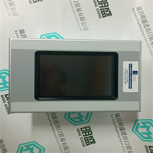
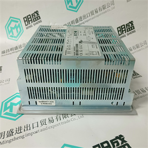
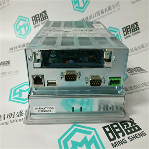
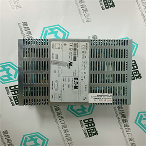
施耐德 140CRA93100 RIO 站适配器S908 单电缆 Schneider
总线终端装置必须始终安装在CEX总线上的后一个装置上,如
如86页图25所示。TB850公CEX总线终端单元为
随每个PM8xx/TP830处理器单元提供。
但是,如果配置需要使用TK850延长电缆,如
如87页图26所示,TB851母CEX总线终端单元为
需要,并且必须安装到顺序中的后一个底板上。TB851女性
每个TK850延长电缆均配有CEX总线终端装置。
TK850 CEX总线延长电缆
任何一条CEX总线中只能使用一条TK850 CEX总线延长电缆。
电缆长度:0.7米(2.3英尺)。
安装CEX总线互连单元BC810/TP857
BC810单元必须直接安装到处理器单元上的CEX总线
底板。SM81x(如果使用)和通信接口安装到
BC810上的CEX总线,每端均端接TB850公CEX总线
终端单元。两个BC810通过互连电缆连接
TK851。
连接到BC810的CEX总线单元的大数量为六个。这个
BC810的主要功能是将CEX总线划分为两个物理上独立的总线
增加系统可用性的段,一个段上出现故障的CEX总线单元
不会影响处理器单元或其他CEX总线段。也是
重要注意:当使用BC810和冗余CEX总线时
单元这些单元应安装在不同的BC810 CEX总线段上。
安装CEX总线互连单元BC810/TP8572节安装
104 3BSE036351-600 A
配置示例请参见106页的图31和107页的图32。
使用符合可用性要求的配置,
AC 800M控制器系统的冗余和安全性。
BC810由处理器单元通过CEX总线或通过以下方式供电:
其外部电源连接器。此外部连接器还可以支持
具有冗余电源的CEX总线。
如果在BC810的冗余配置中使用外部连接器,则有
两种有效连接可能性:
•处理器单元和BC810的单电源(SD8xx或SS8xx)
在两个段(即段A和B)上。参见108页图33。
•段A上处理器单元的一个电源(SD8xx或SS8xx),以及
B段上的BC810,以及用于
段B上的处理器单元和段A上的BC810。参见图34
109页。
不要将用BC810分隔的两个CEX总线段相互连接
带有CEX总线延长电缆TK850。
为了获得冗余电源,将外部连接器连接到
SS82x投票设备。有关SS82x连接的详细信息,请参阅安装
145页的SS823/SS832表决装置。另请参阅外部电源
资料来源:183页。
在AC 800M高完整性控制器中,要求外部电源:
BC810的输入端已连接,电源已严格配置
根据图33或图34,也不允许
例如,通过单个断路器更改配置
模块之间。
2节安装:安装CEX总线互连单元BC810/TP857
3BSE036351-600 A 105
位于主或单个控制器CPU旁边的BC810的热插拔,
否则称为“直接BC810”,可能危及整个控制器和
除非CEX总线上的每个模块都处于非工作状态,否则不应执行。注:在AC 800M HI控制器中,这是无条件的
故意导致控制器关闭。
不位于主或单个控制器CPU旁边的BC810的热插拔,
否则称为“间接BC810”,将关闭任何非冗余接口
位于CEX总线段上,除非:
接口已经处于非操作状态,或者它们的功能对于
控制器。 施耐德 140CRA93100 RIO 站适配器S908 单电缆 Schneider
 施耐德 140CRA93100 RIO 站适配器S908 单电缆 Schneider
bus termination unit must always be fitted to the last unit on the CEX-Bus, as
shown in Figure 25 on page 86. A TB850 male CEX-Bus termination unit is
supplied with each PM8xx/TP830 processor unit.
However, should the configuration require the use of a TK850 extension cable, as
shown in Figure 26 on page 87, then a TB851 female CEX-Bus termination unit is
required and must be fitted to the last baseplate in the sequence. A TB851 female
CEX-Bus termination unit is supplied with each TK850 extension cable.
TK850 CEX-Bus Extension Cable
Only one TK850 CEX-Bus extension cable may be used in any one CEX-Bus.
Cable length: 0.7 m (2.3 ft).
Installing the CEX-Bus Interconnection Unit BC810/TP857
The BC810 units must be mounted directly to the CEX-Bus on the processor unit
base plate. The SM81x, if used, and communication interfaces are then mounted to
the CEX-Bus on the BC810, and terminated in each end with TB850 male CEX-Bus
termination unit. The two BC810 are connected with the interconnection cable
TK851.
The maximum number of CEX-Bus units connected to a BC810 is six. The
primary function of BC810 is to divide the CEX-Bus into two physically separate
segments for increased system availability, a faulty CEX-Bus unit on one segment
will not affect the processor unit or the other CEX-Bus segment. It is also
important to note that when using the BC810 together with redundant CEX-Bus
units these units shall be mounted on different BC810 CEX-Bus segments.
Installing the CEX-Bus Interconnection Unit BC810/TP857 Section 2 Installation
104 3BSE036351-600 A
See Figure 31 on page 106 and Figure 32 on page 107 for configuration examples.
Use the configuration which coincides with the requirements for availability,
redundancy and safety of your AC 800M controller system.
The BC810 is powered either from the processor unit via the CEX-Bus or through
its external connector for power supply. This external connector can also support the
CEX-Bus with redundant power.
If the external connector is used in a redundant configuration of BC810, there are
two valid connection possibilities:
• Single power source (SD8xx or SS8xx) for the processor units and the BC810s
on both the segments (say, segments A and B). See Figure 33 on page 108.
• One power source (SD8xx or SS8xx) for the processor unit on segment A and
the BC810 on segment B, and another power source (SD8xx or SS8xx) for the
processor unit on segment B and the BC810 on segment A. See Figure 34 on
page 109.
Do not connect the two CEX-Bus segments, separated with BC810, to each other
with CEX-Bus extension cable TK850.
For obtaining redundant power supply, connect the external connector to the
SS82x voting device. For details of SS82x connections, see Installing the
SS823/SS832 Voting Unit on page 145. See also Powering from an External
Source on page 183.
In AC 800M High Integrity Controllers it is required that the external supply
input of BC810 is connected and that the power supply is strictly configured
either according to Figure 33 or according to Figure 34 and nor is it allowed to
change the configuration by way of for instance individual circuit breakers
between modules.
Section 2 Installation Installing the CEX-Bus Interconnection Unit BC810/TP857
3BSE036351-600 A 105
Hot swap of the BC810 located next to a primary or single controller CPU,
otherwise called “direct BC810”, might jeopardize the whole controller and
should not be performed unless every module on the CEX-Bus are in a nonoperating state. Note: In an AC 800M HI controller this is unconditionally and
intentionally leading to a shutdown of the controller.
Hot swap of the BC810 not located next to a primary or single controller CPU,
otherwise called “indirect BC810”, will shut down any non-redundant interface
located on that CEX-Bus segment and should not be performed unless such
interfaces already are in a non-operating state or their function is dispensable for
the controller. 施耐德 140CRA93100 RIO 站适配器S908 单电缆 Schneider
| | | |

