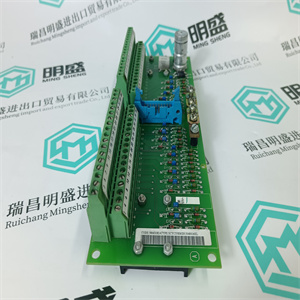
140DDO84300 离散量 DC 输出模块16 点 10-60 VDC Schneider
使用以下步骤连接外部电池单元:
1.将SB821外部电池单元安装在DIN导轨上的适当位置。
2.连接SB821外部电池单元时,使用2米(2.2码)电缆
TK821V020。将一端插入电池单元,另一端插入外部
PM8xx处理器单元的电池电源插座(参见36页图2)。
3.在冗余CPU配置中,包含两个
PM858/PM861/PM862/PM864/PM865/PM866/PM867处理器单元,用于
还有两个SB821电池单元,每个处理器单元一个。
4.由于电池并联,在使用
外部电池,从PM8xx上拆下内部电池,以便
避免减少可用内存和备份时间。
在安装AC 800M控制器之前,不要连接TK821V020电缆
正常通电并且存储器备份功能已被激活,
即,B(电池)LED闪烁。如果未连接正常电源
PM8xx处理器单元,CPU内存将立即开始消耗
连接电缆时的电池电量。
安装结束时,务必安装新的内部或外部电池
阶段由于在运行期间频繁停电,原电池被大量使用
系统安装。
安装SB822可充电外部电池单元2节:安装
152 3BSE036351-600 A
安装SB822可充电外部电池单元
使用以下步骤连接可充电外部电池单元:
1.交付时,锂离子电池组内部未连接。追随
包装箱中的数据和安装表中的步骤:
正确连接电池组。
2.将SB822可充电外部电池单元安装在适当位置
DIN导轨。
3.将24V电源连接至包装箱内的连接器。
4.将24V电源连接到电池单元(X3)
5.确保AC 800M控制器已通电,且电池已接通
PM8xx的前端正在闪烁
6.连接SB822可充电外部电池单元,使用2米(2.2码)
电缆TK821V020。将一端插入电池单元,另一端插入
PM8xx处理器单元的外部电池电源插座(参见上的图2
36页)。
7.确保SB822上的绿色电源指示灯和黄色充电指示灯
被打开。
8.在冗余CPU配置中,包含两个
PM858/PM861/PM862/PM864/PM865/PM866/PM867/PM891处理器
单元,也使用两个SB822电池单元,每个处理器单元一个。
9.由于电池并联,在使用
外部电池,从PM8xx上拆下内部电池,以便
避免减少可用内存和备份时间。
在安装AC 800M控制器之前,不要连接TK821V020电缆
正常通电且存储器备份功能已激活,
B(蓄电池)LED闪烁。如果PM8xx未连接正常电源
处理器单元,CPU内存将立即开始消耗电池电量
连接电缆时
2节安装I/O装置的安装
3BSE036351-600 A 153
I/O装置的安装
有关安装、拆卸和释放程序的更多信息,请参阅
输入/输出装置,请参阅相应的输入/输出系统文档。
柜内安装
下图是AC 800M控制器如何供电的示例
电源单元、表决单元和S800 I/O单元可配置和安装在
橱柜:
•154页图54:壁柜-单电源布置
•155页图55:壁柜-双电源(本地/现场)
安排
•156页图56:落地式机柜-装置布置
(冗余PSU)
DIN导轨采用支撑铝型材,以确保刚性。
参见429页的图124。
图中所示的机柜为ABB制造的机柜:
•RE820:Wa 140DDO84300 离散量 DC 输出模块16 点 10-60 VDC Schneider
 140DDO84300 离散量 DC 输出模块16 点 10-60 VDC Schneider
se the following procedure to connect the external battery unit:
1. Mount the SB821 external battery unit at a suitable position on the DIN-rail.
2. For connecting the SB821 external battery unit, use the 2 m (2.2 yd) cable
TK821V020. Plug one end into the battery unit and the other into the external
battery supply socket of the PM8xx processor unit (see Figure 2 on page 36).
3. In redundant CPU configuration containing two
PM858/PM861/PM862/PM864/PM865/PM866/PM867 processor units, use
also two SB821 battery units, one for each processor unit.
4. Due to the batteries being connected in parallel, it is necessary, when using the
external battery, to remove the internal battery from the PM8xx in order to
avoid reducing available memory back-up time.
Do not connect the TK821V020 cable until the AC 800M Controller has been
powered-up normally and the memory back-up function has been activated,
that is, the B(attery) LED flashes. If no normal power supply is connected to
the PM8xx processor unit, the CPU memory will immediately start to consume
battery power when the cable is connected.
Always install a fresh internal or external battery at the end of the installation
phase. The original battery is heavily utilized due to frequent blackouts during
system installation.
Installing the SB822 Rechargeable External Battery Unit Section 2 Installation
152 3BSE036351-600 A
Installing the SB822 Rechargeable External Battery Unit
Use the following procedure to connect the rechargeable external battery unit:
1. At delivery the Li-Ion battery package is not connected internally. Follow the
steps in the Data and installation sheet, which is enclosed in the packing box, to
connect the battery package properly.
2. Mount the SB822 rechargeable external battery unit at a suitable position on
the DIN-rail.
3. Connect the 24V supply to the connector enclosed in the packing box.
4. Connect the 24V supply to the battery unit (X3)
5. Make sure that the AC 800M controller is powered and that the battery LED in
the front of PM8xx is flashing
6. Connect the SB822 rechargeable external battery unit, use the 2 m (2.2 yd)
cable TK821V020. Plug one end into the battery unit and the other into the
external battery supply socket of the PM8xx processor unit (see Figure 2 on
page 36).
7. Make sure that the green Power LED and the yellow Charge LED on SB822
are turned on.
8. In redundant CPU configuration containing two
PM858/PM861/PM862/PM864/PM865/PM866/PM867/PM891 processor
units, use also two | 140DDO84300 离散量 DC 输出模块16 点 10-60 VDC Schneider | | | |