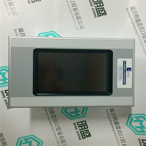
140DRA84000 安装控制继电器输出模块 16 点 Schneider
140DRA84000 安装控制继电器输出模块 16 点 Schneider电缆TK821V020。将一端插入电池单元,另一端插入
PM8xx处理器单元的外部电池电源插座(参见上的图2
36页)。
7.确保SB822上的绿色电源指示灯和黄色充电指示灯
被打开。
8.在冗余CPU配置中,包含两个
PM858/PM861/PM862/PM864/PM865/PM866/PM867/PM891处理器
单元,也使用两个SB822电池单元,每个处理器单元一个。
9.由于电池并联,在使用
外部电池,从PM8xx上拆下内部电池,以便
避免减少可用内存和备份时间。
在安装AC 800M控制器之前,不要连接TK821V020电缆
正常通电且存储器备份功能已激活,
B(蓄电池)LED闪烁。如果PM8xx未连接正常电源
处理器单元,CPU内存将立即开始消耗电池电量
连接电缆时
2节安装I/O装置的安装
3BSE036351-600 A 153
I/O装置的安装
有关安装、拆卸和释放程序的更多信息,请参阅
输入/输出装置,请参阅相应的输入/输出系统文档。
柜内安装
下图是AC 800M控制器如何供电的示例
电源单元、表决单元和S800 I/O单元可配置和安装在
橱柜:
•154页图54:壁柜-单电源布置
•155页图55:壁柜-双电源(本地/现场)
安排
•156页图56:落地式机柜-装置布置
(冗余PSU)
DIN导轨采用支撑铝型材,以确保刚性。
参见429页的图124。
图中所示的机柜为ABB制造的机柜:
•RE820:壁柜
•RM550:落地柜
柜内安装2节安装
154 3BSE036351-600 A
图54.壁柜-单电源布置
24V配电
终端
电源断路器SD831
单元
缆绳
管
铝
轮廓
缆绳
膨胀
模块总线
2节安装:柜内安装
3BSE036351-600 A 155
图55.壁柜-双电源(本地/现场)布置
电源断路器
单元
SD831
24V配电
(单位)
(柜内装置)
SD831
(现场)24V配电(现场设备)安装在电缆连接2安装156 3BSE036351-600A图56。地面安装电缆冗余电源装置现场设备)SD8322节安装正确通风的安装尺寸3BSE0351-600 A 157
适当通风的安装尺寸
为了保持足够的冷却气流通过AC 800M控制器单元,有
装置上方50mm(2英寸)和下方25mm(1英寸)范围内不得有障碍物,
如157页图57所示。请注意,CPU和通信
接口必须安装在水平DIN导轨上。
图57.通风要求-小安装尺寸
>261毫米
(10.3英寸)
>50毫米(2.0英寸)
>50毫米(2.0英寸)
>25毫米(1.0英寸)
>25毫米(1.0英寸)
无障碍区
无障碍区
适当通风的安装尺寸2节:安装
158 3BSE036351-600 A
3BSE036351-600 A 159
3节配置
一般信息
使用工程工具Control Builder,可以配置硬件(I/O
和通信单元),并使用控制语言制作应用程序
根据IEC 61131-3。程序可以离线编译和运行,以帮助
终将应用程序下载到控制器之前的过程模拟。这个
控件生成器提供了一组选项,每个选项都有自己的一组属性。仅仅
选择接近系统要求的选项。
•Control Builder文档–用于配置信息
•控制软件文档——可用功能。
在下列情况下,Control Builder联机帮助提供详细的分步信息:
为AC 800M控制器创建应用程序。
连接控件生成器3节配置
160 3BSE036351-600 A
连接控件生成器
Control Builder安装在通常连接到AC 800M的PC中
控制器通过控制网络和控制器上的CN1或CN2端口
(参见161页图58)。
或者,控制生成器可以通过COM4端口(RS-232C)连接
在AC 800M控制器上。使用工具电缆TK212和PC上的串行端口。
在冗余配置中,控制生成器连接到主CPU
COM4端口。备份CPU无法与Control Builder通信。
PM851/PM851A仅限于一个以太网(CN1)端口,因此是冗余的
以太网不可用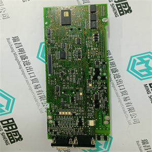
140DRA84000 安装控制继电器输出模块 16 点 Schneider
cable TK821V020. Plug one end into the battery unit and the other into the
external battery supply socket of the PM8xx processor unit (see Figure 2 on
page 36).
7. Make sure that the green Power LED and the yellow Charge LED on SB822
are turned on.
8. In redundant CPU configuration containing two
PM858/PM861/PM862/PM864/PM865/PM866/PM867/PM891 processor
units, use also two SB822 battery units, one for each processor unit.
9. Due to the batteries being connected in parallel, it is necessary, when using the
external battery, to remove the internal battery from the PM8xx in order to
avoid reducing available memory back-up time.
Do not connect the TK821V020 cable until the AC 800M Controller has been
powered-up normally and the memory back-up function has been activated, that is,
the B(attery) LED flashes. If no normal power supply is connected to the PM8xx
processor unit, the CPU memory will immediately start to consume battery power
when the cable is connected
Section 2 Installation Installation of I/O Units
3BSE036351-600 A 153
Installation of I/O Units
For further information regarding mounting, removing and releasing procedures for
I/O Units, refer to the appropriate I/O system documentation.
Installation in Cabinets
The figures listed below are examples of how the AC 800M Controllers, Power
Supply units, Voting units and S800 I/O units can be configured and mounted within
cabinets:
• Figure 54 on page 154: Wall Cabinet – Single Power Supply Arrangement
• Figure 55 on page 155: Wall Cabinet – Dual Power Supply (Local/Field)
Arrangement
• Figure 56 on page 156: Floor Mounted Cabinet – Unit Arrangement
(Redundant PSU)
The DIN-rails are using the supporting Al-profile to ensure rigidness.
See Figure 124 on page 429.
The cabinets shown in the figures are ABB manufactured cabinets:
• RE820: Wall Cabinet
• RM550: Floor Cabinet
Installation in Cabinets Section 2 Installation
154 3BSE036351-600 A
Figure 54. Wall Cabinet – Single Power Supply Arrangement
24 V Distribution
Terminals
Mains Breaker SD831
Unit
Cable
Duct
Aluminum
Profile
Cable
Expansion
ModuleBus
Section 2 Installation Installation in Cabinets
3BSE036351-600 A 155
Figure 55. Wall Cabinet – Dual Power Supply (Local/Field) Arrangement
Mains Breaker
Unit
SD831
24 V Distribution
(Units)
(Units in Cabinet)
SD831
(Field)24VDistribution(FieldEquipment)InstallationinCabinection 2 Installation156 3BSE036351-600AFigure56.FloorMountedCabinetRedundantPowerSupply UnitsFieldEquipment)SD832Section 2 InstallationMounting Dimensions for Proper Ventilation3BSE036351-600 A 157
Mounting Dimensions for Proper Ventilation
To maintain adequate cooling airflow through the AC 800M Controller units, there
must be no obstruction within 50 mm (2 in) above and 25 mm (1 in) below the units,
as shown in Figure 57 on page 157. Note that the CPU and Communication
Interfaces must be mounted on a horizontal DIN-rail.
Figure 57. Ventilation Requirements – Minimum Mounting Dimensions
>261 mm
(10.3 in)
>50 mm (2.0 in)
>50 mm (2.0 in)
>25 mm (1.0 in)
>25 mm (1.0 in)
Unobstructed areas
Unobstructed areas
Mounting Dimensions for Proper Ventilation Section 2 Installation
158 3BSE036351-600 A
3BSE036351-600 A 159
Section 3 Configuration
General Information
Using the engineering tool Control Builder, it is possible to configure hardware (I/O
and communication units) and make application programs with control languages
according to IEC 61131-3. Programs can be compiled and run off-line as an aid to
process simulation before finally downloading an application to the controller. The
Control Builder offers a set of options, each with its own set of properties. Simply
select the option that is closest to system requirements.
• Control Builder documentation – for configuration information
• Control Software documentation – for available functionality.
Control Builder Online Help provides detailed step-by-step information when
creating an application for the AC 800M Controller.
Connecting Control Builder Section 3 Configuration
160 3BSE036351-600 A
Connecting Control Builder
The Control Builder is installed in a PC that is normally connected to the AC 800M
Controller via the Control Network and the CN1 or CN2 ports on the controller
(see Figure 58 on page 161).
Alternatively, the Control Builder may be connected via the COM4 port (RS-232C)
on the AC 800M Controller. Use the tool cable TK212 and a serial port on the PC.
In redundant configuration, the Control Builder is connected to the Primary CPU
COM4 port. The Backup CPU cannot communicate with Control Builder.
PM851/PM851A is restricted to one Ethernet (CN1) port, thus redundant
Ethernet is not available | 140DRA84000 安装控制继电器输出模块 16 点 Schneider | | | |

