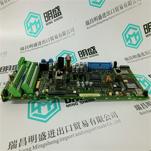
140CPS11400 模拟量Quantum电源模块 115/230 VAC Schneider使用工程工具Control Builder,可以配置硬件(I/O
和通信单元),并使用控制语言制作应用程序
根据IEC 61131-3。程序可以离线编译和运行,以帮助
终将应用程序下载到控制器之前的过程模拟。这个
控件生成器提供了一组选项,每个选项都有自己的一组属性。仅仅
选择接近系统要求的选项。
•Control Builder文档–用于配置信息
•控制软件文档——可用功能。
在下列情况下,Control Builder联机帮助提供详细的分步信息:
为AC 800M控制器创建应用程序。
连接控件生成器3节配置
160 3BSE036351-600 A
连接控件生成器
Control Builder安装在通常连接到AC 800M的PC中
控制器通过控制网络和控制器上的CN1或CN2端口
(参见161页图58)。
或者,控制生成器可以通过COM4端口(RS-232C)连接
在AC 800M控制器上。使用工具电缆TK212和PC上的串行端口。
在冗余配置中,控制生成器连接到主CPU
COM4端口。备份CPU无法与Control Builder通信。
PM851/PM851A仅限于一个以太网(CN1)端口,因此是冗余的
以太网不可用。
3节控制网络的配置连接
3BSE036351-600 A 161
与控制网络的连接
控制网络是实时数据和通用数据的专用IP网络域
工业计算机之间的通信系统。它是可扩展的,从
具有几个节点的小型网络,到包含多个节点的大型网络
“网络区域”和数百个节点。
图58.连接到
在工业环境中,仅
使用STP电缆完全控制
电缆可用。
仅使用
STP内部
有
常见的
接地
工业
环境
非工业
环境
法罗群岛
FO=光纤链路
STP=屏蔽双绞线链路
控制器安装
在柜子里
控制生成器操作员站
例外使用STP
一般使用FO
一般使用STP
FO或STP FO或STP并观察
大限度
电缆长度。
通信可能性3节配置
162 3BSE036351-600 A
网络可以利用不同的混合链路实现,如Fast
以太网和PPP。它提供完全冗余,以实现高网络
可利用性
AC 800M控制器始终通过STP连接到控制网络
(屏蔽双绞线)电缆。当地环境是否应为工业环境
本质上,AC 800M/控制网络连接必须转换为
光纤(FO)电缆。这是通过安装以太网交换机来实现的,该交换机具有:
光端口和电端口。参见161页图58。
有关控制网络的更多信息,请参阅控制网络文档。
通信可能性
处理器单元(PM8XX/TP830或PM891)包含以下内容:
通信端口,提供以下功能:
•CN1和CN2用于连接控制网络。都是RJ45
以太网端口(IEEE802.3)和连接通常使用
5类屏蔽双绞线(STP 5级)。然而,正如所提到的
以前,在工业环境中,建议所有STP
电缆转换为光纤。
–对于单CPU或冗余CPU和单网络:所有CN1端口均为
连接到网络(可以使用CN2,但需要重新配置
有关CPU的通信设置)。
–对于单CPU或冗余CPU和冗余网络:所有CN1端口均为
连接到主网络,所有CN2端口连接到辅助网络
网络
附录C中提供了电缆选择、开关等的详细信息,
推荐组件。
PM851/PM851A仅限于一个以太网(CN1)端口,因此是冗余的
以太网不可用
140CPS11400 模拟量Quantum电源模块 115/230 VAC Schneider
 140CPS11400 模拟量Quantum电源模块 115/230 VAC SchneiderUsing the engineering tool Control Builder, it is possible to configure hardware (I/O
and communication units) and make application programs with control languages
according to IEC 61131-3. Programs can be compiled and run off-line as an aid to
process simulation before finally downloading an application to the controller. The
Control Builder offers a set of options, each with its own set of properties. Simply
select the option that is closest to system requirements.
• Control Builder documentation – for configuration information
• Control Software documentation – for available functionality.
Control Builder Online Help provides detailed step-by-step information when
creating an application for the AC 800M Controller.
Connecting Control Builder Section 3 Configuration
160 3BSE036351-600 A
Connecting Control Builder
The Control Builder is installed in a PC that is normally connected to the AC 800M
Controller via the Control Network and the CN1 or CN2 ports on the controller
(see Figure 58 on page 161).
Alternatively, the Control Builder may be connected via the COM4 port (RS-232C)
on the AC 800M Controller. Use the tool cable TK212 and a serial port on the PC.
In redundant configuration, the Control Builder is connected to the Primary CPU
COM4 port. The Backup CPU cannot communicate with Control Builder.
PM851/PM851A is restricted to one Ethernet (CN1) port, thus redundant
Ethernet is not available.
Section 3 Configuration Connection to a Control Network
3BSE036351-600 A 161
Connection to a Control Network
Control Network is a private IP network domain for both real time data and general
system communication between industrial computers. It is scalable, from a very
small network with a few nodes, to a large network containing a number of
“Network Areas” and many hundreds of nodes.
Figure 58. Example of AC 800M Controllers Connected to a
Within industrial environments, only
use STP cable where full control of
the cabling is available.
Use only
STP inside
areas with
common
grounding
INDUSTRIAL
ENVIRONMENT
NON-INDUSTRIAL
ENVIRONMENT
FO
FO = Fiber Optic link
STP = Shielded Twisted Pair Link
Controllers mounted
in cabinets
Control Builder Operator Station
USE STP EXCEPTIONALLY
USE FO GENERALLY
USE STP GENERALLY
FO or STP FO or STP and observe
maximum
cable length.
Communication Possibilities Section 3 Configuration
162 3BSE036351-600 A
The network can utilize different and mixed link implementations such as Fast
Ethernet and PPP. It provides for full redundancy, in order to achieve high network
availability.
The AC 800M controller is always connected to the Control Network via an STP
(Shielded Twisted Pair) cable. Should the local environment be of an industrial
nature, the AC 800M / Control Network connection must be converted over to a
Fiber Optic (FO) cable. This is achieved by installing an Ethernet Switch having
both optical and electrical ports. See Figure 58 on page 161.
For more information on Control Network, see Control Network documentation.
Communication Possibilities
The processor unit (PM8XX/TP830 or PM891) contains the following
communication ports, offering the following functions:
• CN1 and CN2 are used for connection to the Control Network. Both are RJ45
ports for Ethernet (IEEE802.3) and connection is normally achieved using
category 5 shielded twisted pair cable (STP class 5). However, as mentioned
previously, within industrial environments it is recommended that all STP
cables are converted to optical fiber.
– For single or redundant CPUs and single networks: All CN1 ports are
connected to the network (CN2 can be used, but requires reconfiguration
of the communication set-up for the concerned CPU).
– For single or redundant CPUs and redundant networks: All CN1 ports are
connected to the primary network and all CN2 ports to the secondary
network.
Details on cable selection, switches and so forth, are provided in Appendix C,
Recommended Components.
PM851/PM851A is restricted to one Ethernet (CN1) port, thus redundant
Ethernet is not available
140CPS11400 模拟量Quantum电源模块 115/230 VAC Schneider
| | | |