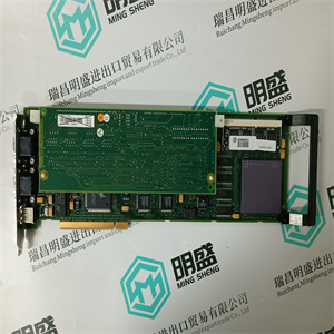


140SAI94000S 安全型模拟量输入PLC模块 Schneider
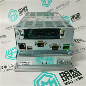
在上面 控制器IP地址 单CPU配置 控制器上CN1端口的IP地址使用IPConfig工具设置(此 工具与800xA系统一起安装)。请参阅IPConfig联机帮助。 如果使用网络冗余,请确保CN1端口连接到 并且CN2端口连接到辅助网络。在这个 在这种情况下,您还必须为CN2端口设置IP地址。请参阅IPConfig联机帮助。 冗余CPU配置 在具有冗余CPU的配置中,IP地址必须设置如下: 1.关闭备用CPU(电源关闭)。 2.将IPConfig工具连接到主CPU,并设置 主CPU上的CN1端口。请参阅IPConfig联机帮助。 如果冗余控制器(PM8XX)与冗余通信一起使用 接口,确保完全冗余并支持在线升级 固件。 建议采用以下方式启动IPConfig会话: 在分配预期IP地址之前,执行“恢复出厂设置”命令。 这将删除以前存储的备用MAC和IP地址(如果有)。看见 53页冗余配置中的MAC和IP地址处理。 在Control Builder中设置主CPU的IP地址时 备份CPU必须关闭(断电)。否则,备份CPU 会接管,你会断开连接。 一次加电时,主处理器始终是连接到 RCU链路接头标记为“上部”。 如果使用网络冗余,则主设备的CN2端口的IP地址 无法使用IPConfig设置处理器。必须在控制中设置此地址 建设者 I/O系统3节配置 166 3BSE036351-600 A 3.设置备份CPU上CN1端口的IP地址。使用默认设置 (0.0.2.0添加到主CPU的地址),除非您的网络 管理员另有要求。请参阅IPConfig联机帮助。 4.开始您的800xA工作场所。 5.在Project Explorer硬件树中创建控制器的表示。 确保PM858/PM861/PM862/PM864/PM865/PM866/PM867/PM891 处理器单元定义为冗余。请参阅控件生成器联机帮助。 6.在Project Explorer中,将控制器的IP地址设置为 主CPU。请参阅控件生成器联机帮助。 7.打开辅助CPU。检查您是否与 控制器。 输入/输出系统 有几种方法将I/O系统连接到AC 800M控制器: •通过CI856的S100输入/输出。 •通过模块总线的S800输入/输出单元。支持运行期间的热配置, 各级冗余、HART路由和事件顺序(SOE)。 •通过CI854/CI854A/CI854B和CI840/CI840A、PROFIBUS的S800输入/输出单元 DP。支持HART路由、各级冗余和热配置 在运行期间。 •通过CI854/CI854A/CI854B和CI801、PROFIBUS DP的S800输入/输出单元。支持 用于运行期间的HART路由和热配置。 •S900输入/输出装置可连接到PROFIBUS DPFor information on available serial protocols for the CI853 interface, see COM3 above. Controller IP Addresses Single CPU Configurations The IP address of the CN1 port on the controller is set using the IPConfig tool (this tool is installed together with the 800xA system). See IPConfig online help. If network redundancy is used, make sure that the CN1 port is connected to the primary network, and the CN2 port is connected to the secondary network. In this case, you also have to set the IP address for the CN2 port. See IPConfig online help. Redundant CPU Configurations In configurations with redundant CPU, the IP address must be set as follows: 1. Switch off the backup CPU (power down). 2. Connect the IPConfig tool to the primary CPU and set the IP address of the CN1 port on the primary CPU. See IPConfig online help. If redundant controllers (PM8XX) are used along with redundant communication interfaces, it ensures full redundancy and supports the online upgrade of firmware. It is recommended to make a practice of always starting an IPConfig session with a “Restore factory settings” command before assigning the intended IP addresses. This will erase previously stored alternative MAC and IP addresses if any. See MAC and IP Address Handling in Redundant Configuration on page 53. When setting the IP address of the primary CPU in Control Builder, the backup CPU must be turned off (powered down). Otherwise the backup CPU will take over and you get disconnected. At the first power-up, the primary processor is always the one connected to the RCU Link connector marked “UPPER”. If network redundancy is used, the IP address of the CN2 port of the primary processor cannot be set using IPConfig. This address must be set in Control Builder I/O Systems Section 3 Configuration 166 3BSE036351-600 A 3. Set the IP address of the CN1 port on the backup CPU. Use default settings (0.0.2.0 is added to the address of the primary CPU), unless your network administrator requires otherwise. See IPConfig online help. 4. Start your 800xA Workplace. 5. Create a representation of the controller in the Project Explorer hardware tree. Make sure the PM858/PM861/PM862/PM864/PM865/PM866/PM867/PM891 processor unit is defined as redundant. See Control Builder online help. 6. In Project Explorer, set the IP address of the controller to the IP address of the primary CPU. See Control Builder online help. 7. Switch on the secondary CPU. Check that you have communication with the controller. I/O Systems There are several methods of connecting I/O systems to the AC 800M Controller: • S100 I/O via CI856. • S800 I/O units via the ModuleBus. Support for hot configuration during run, redundancy on all levels, HART routing, and Sequence-of-Events (SOE). • S800 I/O units via CI854/CI854A/CI854B and CI840/CI840A, PROFIBUS DP. Support for HART routing, redundancy on all levels, and hot configuration during run. • S800 I/O units via CI854/CI854A/CI854B and CI801, PROFIBUS DP. Support for HART routing, and hot configuration during run. • S900 I/O units can be connected to PROFIBUS DP |
Copyright ©2019-2022 瑞昌明盛自动化设备有限公司 版权所有 赣ICP备2021006016号