575-2103 SIMATIC 575 控制器主驱动扩24V直流配电系统电缆必须采用熔断器保护。为了允许
在过载/短路情况下,电源输出电流受到限制。允许
电源的额外容量至少为额定电流值的3-4倍
大连接保险丝,请记住在
计算
连接备选方案
现场设备电源的连接方式与使用的方式相同
用于连接交流800M装置并为其供电(参见184页图66和
185页图67)。但是,应注意,相同的电源断路器
该装置可用于控制和隔离两个电源。或者,
每个支路上可使用独立的电源断路器(参见185页图67)。
3节配置:从外部电源供电
3BSE036351-600 A 183
从外部电源供电
AC 800M控制器可由外部+24V直流电源供电。这
对于许多不同类型的工厂设备,源通常是常见的,导致
连接AC 800M控制器的长电源电缆。此外,重载变化可以
导致控制器电源电压变化,因此需要采取预防措施
以防止控制器故障。
如果PM8XX电源端子处存在+24 V电压下降的风险
低于19.2 V持续1 ms以上,则必须使用储能器
动力装置。
ABB要求在以下情况下使用DC/DC转换器和额外的储能器:
使用电缆长度超过10m的外部直流电源。
对于AC 800M控制器和相关单元的冗余电源,
始终从SS8xx投票设备导出连接。参见页的图66
184
从外部电源供电3节配置
184 3BSE036351-600 A
图66.AC 800M装置的电源选项
单位
供应
设备8xx电源24 V直流配电配电监视冗余电源冗余市电电源终端
24 V直流配电终端24 VDCD配电终端8xxs电源D8xxsD8xxS8xxs设备8xxsS8xxx主断路器主断路器断路器主电源
电源3节配置从外部电源供电3BSE036351-600 A 185
图67.为现场设备供电现场设备8xxSd8xXU用于24伏直流配电24伏直流电配电独立8xSdM主断路器主断路器用于24伏交流配电
独立的
电源
独立电源
断路器单元
电源断路器
干线
终端
终端
终端
终端
电源
领域
设备
供应
8xx
SD
为现场设备供电
从外部电源供电3节配置
186 3BSE036351-600 A
3BSE036351-600 A 187
4节操作
本节描述了AC 800M控制器的操作,包括
PM8xx(单或冗余配置)处理器单元,以及各种
可选单元。有关可选装置的更多技术信息,请参见附录
A、 硬件单元。
AC 800M控制器(PM8xx)
配备控制软件的基本PM8xx/TP830或PM891硬件单元
安装在AC 800M硬件平台上,构成AC 800M控制器。
AC 800M控制器(PM8xx)4节操作
188 3BSE036351-600 A
LED指示灯
有关放置的说明,请参见36页的图2。
表19.PM8xx–LED指示灯
标记颜色函数
F(故障)红色正常状态-关闭
重新启动(初始化)临时点亮F(故障)。
也可以通过软件在以下过程中进行操作:
特殊状态,例如:
固件升级。
R(un)绿色正常状态–打开(当应用程序
执行)
临时冷重启(短初始化)
熄灭R(un)。
控制器复位(长初始化,3秒或更长)
R(un)闪烁,直到INIT按钮
释放。
P(电源)绿色正常状态–开启
点亮时,表示CPU DC/DC
转换器正在生成有效的+5 V和+3.3 V
直流电源电压。
没有软件控制。
B(蓄电池)绿色正常状态–开启
当内部或外部蓄电池电压为
高于3.1 V。LED由
软件电池电压测试(1)。
Tx黄色
绿色(2)
数据传输(4),
CN1+CN2和COM3(3)+COM4
与Tx流量同步闪烁
Rx黄色
绿色(2)
数据接收(4),
CN1+CN2和COM3(3)+COM4
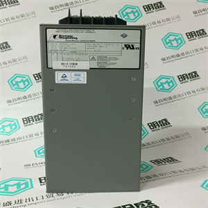
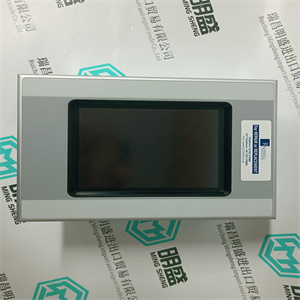
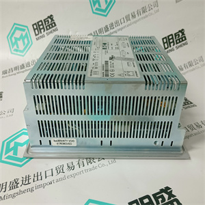
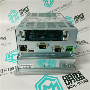
与接收流量同步闪烁展卡 SIEMENS
575-2103 SIMATIC 575 控制器主驱动扩展卡 SIEMENS
 575-2103 SIMATIC 575 控制器主驱动扩展卡 SIEMENS
24 V DC distribution system cables must be fuse-protected. In order to allow for
overload/short circuit situations, the power supply output current is limited. Allow
the power supply an extra capacity of at least 3-4 times the rated current value of the
largest connected fuse and remember to include long cable resistance in the
calculation.
Connection Alternatives
The field equipment power supply can be connected in the same manner as that used
for connecting and powering the AC 800M units (see Figure 66 on page 184 and
Figure 67 on page 185). However, it should be noted that the same Mains Breaker
Unit can be used to control and isolate both power supplies. Alternatively,
independent Mains Breakers can be used on each spur (see Figure 67 on page 185).
Section 3 Configuration Powering from an External Source
3BSE036351-600 A 183
Powering from an External Source
The AC 800M Controller can be powered from an external +24 V DC source. This
source is often common for many different types of plant equipment, resulting in
long power cables to the AC 800M Controller. Furthermore, heavy load changes can
cause variations in controller supply voltage making it necessary to take precautions
against low voltage in order to prevent controller malfunction.
Should there be a risk that the +24 V at the PM8XX power terminals could drop
below 19.2 V for more than 1 ms, then an energy reservoir must be used for
Powering Units.
ABB requires the use of DC/DC converter and extra energy reservoir in case
external DC-supply with longer cables than 10 m is used.
For redundant power supplies to the AC 800M controller and associated units,
always derive connections from the SS8xx voting device. See Figure 66 on page
184.
Powering from an External Source Section 3 Configuration
184 3BSE036351-600 A
Figure 66. Power Supply Options for AC 800M Units
Units
Supply to
Device 8xxSuppliesPower24 V DCDistributionSDVotingRedundant Power SuppliesRedundant Mains Power SuppliesTerminals
24 V DCDistributionTerminals24 VDCDistributionTerminals8xxSupplyPowerSD8xxSD8xxS8xxSSDeviceVoting8xxSS8xxMainsMainsBreakerMainsBreaerMainsSinglPoerSupplyPower
SuppliesSection 3 Configuration Powering from an ExternalSource3BSE036351-600 A 185
Figure 67. PoweringFieldEquipmentFieldEquipment8xxSD8xxUnitsSuly toSupply to24 V DCDistribution24 VDCDistributionIndependent8xxSDMainsMainsBreakerMaisBreakerSupply toUnits24 V DCDistribution24 V DC
ndependent
Power Supplies
Independent Mains
Breaker Units
Mains Breaker
Mains
Terminals
Terminals
Terminals
Terminals
Power Supplies
Field
Equipment
Supply to
8xx
SD
Powering Field Equipment
Powering from an External Source Section 3 Configuration
186 3BSE036351-600 A
3BSE036351-600 A 187
Section 4 Operation
This section describes the operation of the AC 800M Controller, comprising a
PM8xx (single or redundant configuration) processor unit, together with various
optional units. For additional technical information on optional units, see Appendix
A, Hardware Units.
AC 800M Controller (PM8xx)
Equipped with Control Software, the basic PM8xx/TP830 or PM891 hardware units
mounted on the AC 800M hardware platform constitute an AC 800M Controller.
AC 800M Controller (PM8xx) Section 4 Operation
188 3BSE036351-600 A
LED Indicators
See Figure 2 on page 36, for description of placement.
Table 19. PM8xx – LED Indicators
Marking Color Function
F(ault) Red Normal state – OFF
Re-start (INIT) temporarily lit F(ault).
May also be operated by software during
special states such as for instance
FW-upgrade.
R(un) Green Normal state – ON (When application is
executing)
Cold Restart (Short INIT) temporarily
extinguishes R(un).
Controller Reset (Long INIT, 3 sec. or more)
R(un) flashes until INIT push button is
released.
P(ower) Green Normal state – ON
When lit, indicates that the CPU DC/DC
converter is generating valid +5 V and +3.3 V
DC supply voltages.
No software control.
B(attery) Green Normal state – ON
Lit when internal or external battery voltage is
above 3.1 V. The LED is controlled by a
software battery voltage test(1).
Tx Yellow
Green(2)
Data Transmission(4),
CN1 + CN2 and COM3(3) + COM4
Flashes in synchronization with Tx traffic
Rx Yellow
Green(2)
Data Reception(4),
CN1 + CN2 and COM3(3) + COM4
Flashes in synchronization with Rx traffic 575-2103 SIMATIC 575 控制器主驱动扩展卡 SIEMENS
| | | |