
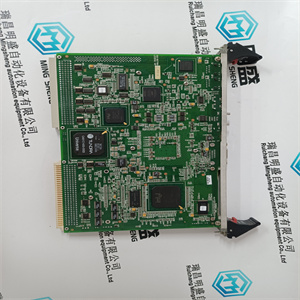


产品标题:NMI-9283-90 A144942 可用于DCS系统控制终端显示器 HMW
型号: NMI-9283-90 A144942 可用于DCS系统控制终端显示器
品牌: HMW
质保:七天验收期,质保期一年
发货期:1-3个工作日
产品图片展示
产品详情资料
塑料保护罩
C2b用于防止
电击五大功率
转换器下端的端子。它每侧都有一个孔,在安装过程中,该孔将卡入转换器每侧面板的压入螺母。III 2-53ADW000165R0201_Technical_Data_e_B模块A5DCS 50x-0903DCS 50x-1203DCS 50x-1503DCS 50x-2003尺寸,单位为毫米重量。110kgfig。2.1/6:尺寸图A5模块母线,单位mm:DC 80 x 10AC 60 x 5DCS 500,适用于DCS 500B/DCS 600*3钻孔,将CDP312面板固定在盖子上;面板通过面板延长电缆(3m)进行电气连接
将转换器模块A5安装在外壳内
外壳内部应安装两个支架,以确保:
在以后放置转换器时,可以承载转换器的重量。支架之间的小距离不应小于480 mm,因为
电气间隙(直流母线)。
如图所示,L形支架将允许临时放置转换器
靠近支架前端(重量仍由提升装置承受),以及
然后将其推回外壳的背板。上下孔
应使用转换器背板中的固定装置将转换器固定在该位置。
*3.钻孔将CDP312面板固定在盖子上;小组
通过面板延长电缆(3m)进行电气连接
*
三、2-7
3ADW000165R0201_Technical_Data_e_b
DCS 500适用于DCS 500B/DCS 600
将转换器模块A6安装在外壳内
转换器设计为放置在底板或类似物上,然后固定在外壳背板的顶部,以避免移动
在前面、右边或左边。此外,转换器应使用细长孔前面的两个支架固定在底部。
冷却空气入口
冷却风扇从背面吸入空气
侧面和转换器下方区域
单元
冷却空气出口
为避免外壳内空气循环,应:
建议确保废气排出
A6_cable_term_busb.dsf
电力电缆连接
通过A6的端子选项01进行电力电缆连接。该选项包括五个选项
角铜母线和五倍四螺钉。这个
机械细节如下图所示。
安装直角母线或连接时
直接连接电缆。请确保使用正确的螺钉
习惯于转换器模块配备有盲板
孔和在其端部的螺母。因此,长度
剩余螺纹限制为35 mm(见下图)。
转换器模块周围的自由空间
佳折衷
俯视图俯视图
图2.1/8:冷却空气流量
图2.1/11:自由空间
图2.1/9:直角铜母线
图2.1/10:剩余螺纹长度
图2.1/13:右侧连接示例
468.2
136
图2.1/12给出了一个示例
如果所有电缆连接仍在转换器左侧,则可以安装母线
单元这导致了电源的四层
电缆。
如果是交流或直流连接,或者可能是两者
它们必须位于c的右侧The plastic protection cover for
C2b serves as a protection against
electric shock for the five high-power
terminals at the lower end of the converter. It is equippedwith a hole oneach side, which will snap-in duringmounting at a press-in nut at eachside panel of the converter.III 2-53ADW000165R0201_Technical_Data_e_bModule A5DCS 50x-0903DCS 50x-1203DCS 50x-1503DCS 50x-2003Dimensions in mmWeight appr. 110 kgFig. 2.1/6: Dimension drawing A5-ModuleBusbars in mm:DC 80 x 10AC 60 x 5DCS 500 valid for DCS 500B / DCS 600* 3 drill holes to fix the CDP312 panel on the cover; panel tobe connected electrically via panel extension cable (3 m)
Mounting the converter module A5 inside an enclosure
Two supports should be mounted inside the enclosure in such a way, that they
can carry the converter's weight when placing the converter later on. The minimum distance between the supports should not be less then 480 mm because
of electrical clearance (DC busbars).
A L-shape support as indicated will allow to place the converter temporarily
close to the front end of the support (weight still taken by a lifting device) and
then push it back to the back plate of the enclosure. The upper and lower holes
in the back plate of the converter should be used to fix the converter in that position.
* 3 drill holes to fix the CDP312 panel on the cover; panel to
be connected electrically via panel extension cable (3 m)
*
III 2-7
3ADW000165R0201_Technical_Data_e_b
DCS 500 valid for DCS 500B / DCS 600
Mounting the converter module A6 inside an enclosure
The converter is designed to be placed on a bottom plate or similar and then fixed on top to the enclosure's back plate to avoid movements
to the front, right or left side. In addition to that the converter should be fixed at the bottom using two brackets in front of the elongated holes.
Cooling air entry
The cooling fan takes the air from the backside, both
sides and from the area underneath the converter
module.
Cooling air outlet
To avoid circulating air inside the enclosure it is
recommended to make sure the exhaust air leaves
A6_cable_term_busb.dsf
Power cable connection
The power cable connection is performed via Terminal option 01 for A6. This option consists of five right
angle copper busbars and five times four screws. The
mechanical details are shown by the figure below.
When mounting the right angle busbars or connecting
cables directly please make sure the right screws are
used. The converter module is equipped with a blind
hole and a nut at its end. Because of that the length of
the remaining threads is limited to 35 mm (see drawing below).
Free space around the converter module
optimum compromise
Top view Top view
Fig. 2.1/8: Cooling air flow
Fig. 2.1/11: Free space
Fig. 2.1/9: Right angle copper busbar
Fig. 2.1/10: Length of remaining threads
Fig. 2.1/13: Example right side connection
468.2
136
Fig. 2.1/12 gives an example, how the right angle
busbars can be mounted in case all cable connections are still made at the left side of the converter
module. This results in four layers for the power
cables.
In case the AC or DC connection or perhaps both of
them have to be made at the right side of the c
主营产品简介
专注于DCS、PLC、机器人控制系统、大型伺服四大系统领域。
主营产品各种模块/卡件,控制器,触摸屏,伺服驱动器。
优势:供应进口原装正品,专业停产配件,
发货快,货期精准,
主营品牌包括 ABB贝利、GE/FUANC、FOXBORO、英维思TRICONEX 、本特利BENTLY、A-B罗克韦尔、艾默生EMERSON 、OVATION、MOTOROLA、XYVOM、霍尼韦尔HONEYWELL 、力士乐REXROTH、KUKA、NI、DEIF、横河、伍德沃德WOODWARD、瑞恩、施耐德SCHNEIDER 、安川、 穆格MOOG、PROSOFT等品牌
Copyright ©2019-2022 瑞昌明盛自动化设备有限公司 版权所有 赣ICP备2021006016号


