


产品标题:M0066932.01 SZM 用于驱动控制输入安全模块 SCHENCK
型号:M0066932.01 SZM 用于驱动控制输入安全模块 SCHENCK
品牌:M0066932.01 SZM 用于驱动控制输入安全模块 SCHENCK
质保:七天验收期,质保期一年
发货期:1-3个工作日
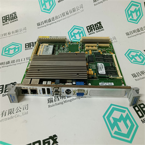
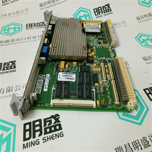
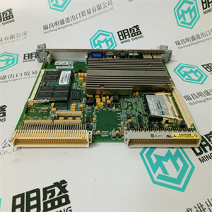
产品图片展示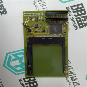
产品详情资料
F 7127、F 7131(发光LED指示正确的模块,暗LED指示有缺陷
单元只更换有缺陷的模块,否则PES将关闭!)
2.如果LED熄灭,检查24 VDC馈电。
3.在拆除故障电源F 7126、F 7130A之前,检查所有电源的输出电压
其他电源(参见数据表)。
4.拧下故障电源并将其拆下。
插入:
1.插入电源并用螺钉固定,
2.检查输出电压(参见数据表)。
注:如果在未关闭的情况下拆除模块
所有I/O子架均已关闭。这将导致MS和
HS系统。
注:在冗余系统中,新插入的中央模块必须具有
操作系统版本与已插入的中央处理器相同
单元如果不是这样,显示屏上会显示一条错误消息
新插入的中央模块,此模块将进入
停止状态。那么相应的操作系统版本必须
加载。因此,请注意操作中的信息
系统手册。
安装和连接
31
8.2.5通信和协处理器模块
删除:
1.断开通信电缆。
2.重要提示:拆下固定螺钉后,首先拆下相关中央模块,
3.拆除通信模块(连接HSR电缆的以太网模块,如果存在)
拆下固定螺钉后,
4.以太网模块:拆除HSR电缆。
插入:
1.根据数据表检查开关的设置,
2.插入不带电缆的模块并固定,
3.以太网模块:连接HSR电缆(仅在HIPRO-S处,但不在HIPROS-DIRECT处),
4.连接通信电缆,
5.插入附属中央模块并用螺钉固定。
8.3 24 VDC系统电压的接地
请注意SELV(安全特低电压)或PELV(保护
超低电压)。为了提高电磁兼容性,提供了仪表接地。仪表接地在机柜内设计为满足保护接地的要求。
所有H41q/H51q系统均可在接地L-或不接地的情况下运行。
8.3.1浮式供应
如果存在多个未检测到的接地故障,可能会触发故障控制信号。为了防止这种情况,
在任何情况下,都必须提供接地故障监测系统(参考
如VDE 0116)。接地故障监测必须安装在控制柜外部。
只能通过关闭部分功能(线路分离)来定位接地故障。一
如果两极都馈电给输出电路,则可以检测到接地故障。
8.3.2接地操作
前提是接地条件良好,并且有一个单独的接地连接(如果可能),没有外部电流流过。仅负极接地
(L-)是允许的。不允许L+正极接地,因为传感器线路上的任何接地故障都会导致相关传感器超控。
L-只能在系统内的一点接地。通常L-直接在后面接地
电源(例如,在母线上)。接地应易于接近和断开。
接地电阻a, F 7127, F 7131 (luminated LEDs indicate correctmodules, dark LED indicate defective
module. Change only defectivemodule, otherwise the PES will switch off!)
2. If the LED is off check the 24 VDC feeding.
3. Before removing the faulty power supply F 7126, F 7130A check the output voltages of all
other power supplies (cf. data sheets).
4. Screw off the faulty power supply and remove it.
Insert:
1. Insert power supply and fix it by screws,
2. Check the output voltage (cf. data sheet).
Note If the module is removed without switching off, the watchdog signal for
all I/O subracks is shut down. This results in an error stop for MS and
HS systems.
Note At redundant systems the new inserted central module must have the
same operating system version as the already plugged central
module. If this is not the case, an error message appears in the display
of the new plugged central module and this module will go into the
STOP state. Then the corresponding operating system version must
be loaded. Please regard therefore the informations in the operating
system manual.
Installation and Connections
31
8.2.5 Communication and Coprocessor Modules
Remove:
1. Disconnect the communication cable.
2. Important: At first remove the appertaining central module after removing the fixing screws,
3. remove communication module (Ethernet module with HSR cable connected, if existing)
after removing the fixing screws,
4. Ethernet module: Remove HSR cable.
Insert:
1. Check settings of the switches according to the data sheet,
2. insert module without cable and fix it,
3. Ethernet module: Connect HSR cable (only at HIPRO-S, but not at HIPRO-S-DIRECT),
4. connect communication cable,
5. insert appertaining central module and fix it by screws.
8.3 Earthing of the 24 VDC System Voltage
Please regard the requirement of the SELV (Safety Extra Low Voltage) or PELV (Protective
Extra Low Voltage). To improve the electromagnetic compatibility an instrument earth is provided. The instrument earth is designed within the cabinet in such a way that it fulfills the requirements of a protection earth.
All H41q/H51q systems can be operated with earthed L- or not earthed.
8.3.1 Floating Supply
With several undetected earth faults faulty control signals may be triggered. To prevent this,
with floating operation in any case an earth fault monitoring system must be provided (ref. also
to e.g. VDE 0116). The earth fault monitoring must be installed outside the control cabinet.
An earth fault can only be located by switching off a partial function (separation of lines). An
earth fault can be detected if both poles are feed to supply an output circuit.
8.3.2 Earthed Operation
It is premised that the earthing conditions are excellent and there is a separate earth connection (if possible) through which no external currents flow. Only the earthing of the negative pole
(L-) is permitted. Earthing of the L+ positive pole is not admissible, as any earth fault on a sensor line would result in an overriding of the sensor concerned.
L- may only be earthed at one point within the system. Generally L- is earthed directly behind
the power supply (e.g. on the bus bar). The earthing should be easy to access and disconnect.
The earthing resista
主营产品简介
专注于DCS、PLC、机器人控制系统、大型伺服四大系统领域。
主营产品各种模块/卡件,控制器,触摸屏,伺服驱动器。
优势:供应进口原装正品,专业停产配件,
发货快,货期精准,
主营品牌包括 ABB贝利、GE/FUANC、FOXBORO、英维思TRICONEX 、本特利BENTLY、A-B罗克韦尔、艾默生EMERSON 、OVATION、MOTOROLA、XYVOM、霍尼韦尔HONEYWELL 、力士乐REXROTH、KUKA、NI、DEIF、横河、伍德沃德WOODWARD、瑞恩、施耐德SCHNEIDER 、安川、 穆格MOOG、PROSOFT等品牌
Copyright ©2019-2022 瑞昌明盛自动化设备有限公司 版权所有 赣ICP备2021006016号


