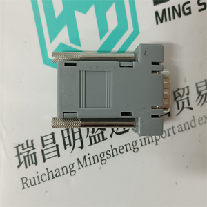
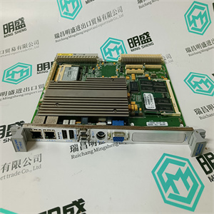
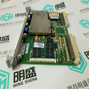
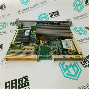


产品标题:IPC40.2G4A-512N-P8C-ND-NN-FW 伺服驱动计算机 Rexroth
型号:IPC40.2G4A-512N-P8C-ND-NN-FW 伺服驱动计算机
品牌: Rexroth
质保:七天验收期,质保期一年
发货期:1-3个工作日
产品图片展示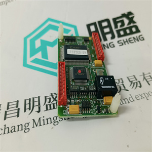
产品详情资料
推荐的启动和维护设备
–PC,作为便携式计算机(笔记本电脑)用于现场工作。系统中的所有项目
当前状态和HIMA系统软件应位于硬盘上,
–带电阻表的高电阻万用表,
–模拟模拟信号的传感器。
9.2安装系统
交付控制柜时,模块插入并用螺钉固定
空闲连接器。它们已经在工厂用这些模块进行了测试,因此
测试集中在正确的外部安装上。
9.3 24 VDC系统电压接地
请参阅第8.2章。
9.4启动控制柜
9.4.1测试外部电压的所有输入和输出
不允许的外部电压(尤其是230 VAC接地或L-)可以用
万用表。我们建议检查每个连接是否存在不允许的外部电压。
9.4.2测试接地故障的所有输入和输出
当测试外部电缆的绝缘电阻、短路和断线时
电缆两端必须断开,以避免损坏或破坏电压过高的模块。
接地故障测试在断开
传感器和控制元件。电势上自由连接器的电压连接
分配器也必须断开。传感器电源必须断开
以及控制元件处的负极必须分开。
如果将负极设置为接地操作,则必须中断接地连接
同时测试接地故障。这也适用于可能存在的接地连接
接地故障测试设施。
可以使用电阻计或专用测试设备测试任何接地连接。
启动和维护
40
9.5接通电源
输入/输出模块及其附属电缆连接器用螺钉固定。这个
在24 VDC工作电压之前,必须检查其极性、电平和纹波是否正确
有联系的。
在极性相反的情况下,保险丝可保护I/O模块免受损坏。
9.6功能测试
9.6.1准备功能测试
对于功能测试,请借助
标签和/或文档打印输出“I/O子架”。输入/输出模块的所有自由连接器必须连接到分配的输入/输出机架
分配的电压分配器的电缆连接器。所有控制元件(控制装置)
必须由工厂管理层释放或无辅助电源驱动。
9.6.2中央设备测试
H41q/H51q系统中央设备的基本测试包括:
我们建议在
并将副本保存在柜门的口袋中。应该
必须交换模块,因此必要的信息将立即可用。
注:在此状态下,系统设置用于测试单个线路或组
线路对地绝缘,但如果两条线路绝缘则不绝缘
彼此对抗。否则有损坏的风险。
测试电压和绝缘电阻的指南是IEC/EN
61131-2或DIN VDE 0160/EN 50178Recommended Devices for Startup and Maintenance
– PC, for the work on site as portable computer (laptop). All projects of the system in their
current state and the HIMA system software should be on the hard disk,
– High resistance multimeter with resistance meter,
– Sensors to simulate analog signals.
9.2 Installing the System
The control cabinets are delivered with the modules plugged in and fixed with screws, and with
free connectors. They have been tested with these modules in the factory, so that the following
tests concentrate on the correct external installation.
9.3 Earthing the 24 VDC System Voltage
Refer to chapter 8.2.
9.4 Starting up the Control Cabinet
9.4.1 Testing All Inputs and Outputs for External Voltage
Impermissible external voltages (especially e.g. 230 VAC to earth or L-) can be measured with
a multimeter. We recommend checking each connection for impermissible external voltage.
9.4.2 Testing All Inputs and Outputs for Earth Faults
When testing the external cables for insulating resistance, short-circuits and wire breaks, the
cables must be disconnected at both ends in order to avoid damaging or destroying the modules with excessive voltage.
The testing for earth faults is carried out after the disconnection of the free connectors for the
sensors and control elements. The voltage connections of the free connectors on the potential
distributors must also be disconnected. The supplies of the sensors must be disconnected as
well as the negative pole must be separated at the control elements.
If the negative pole is set up for earthed operation, the earth connection must be interrupted
while testing for earth faults. This also applies for the earth connection of possibly existing
earth fault testing facilities.
Any connection can be tested to earth with a resistance meter or a special testing device.
Startup and Maintenance
40
9.5 Switching on Power Supply
The input/output modules and their appertaining cable connectors are fixed with screws. The
24 VDC operation voltage has to be checked for correct polarity, level and ripple before it is
connected.
In case of reverse polarity a fuse protects the I/O module of damages.
9.6 Functional Testing
9.6.1 Preparing Functional Testing
For functional testing check the equipment of the control cabinet completely with help of the
label and/or documentation printout "I/O subrack". All free connectors of the input/output modules have to be connected to the allocated input/output racks, and the voltage connections of
the cable connectors to the allocated voltage distributors. All control elements (control devices)
must be released by the factory management or be driven without auxiliary power.
9.6.2 Testing in the Central Devices
The essential tests in the central devices of the H41q/H51q system are:
We recommend marking all required switch positions etc. in copies of the data sheets of the
respective control cabinet and keeping the copies in the pocket of the cabinet door. Should
modules have to be exchanged, the necessary information will thus be immediately available.
Note In this state the system is set up for testing if individual lines or a group
of lines are insulated against earth, but not if two lines are insulated
against each other. Otherwise there is a risk of damage.
The guideline for test voltages and insulating resistance is IEC/EN
61131-2 or DIN VDE 0160/EN 50178
主营产品简介
专注于DCS、PLC、机器人控制系统、大型伺服四大系统领域。
主营产品各种模块/卡件,控制器,触摸屏,伺服驱动器。
优势:供应进口原装正品,专业停产配件,
发货快,货期精准,
主营品牌包括 ABB贝利、GE/FUANC、FOXBORO、英维思TRICONEX 、本特利BENTLY、A-B罗克韦尔、艾默生EMERSON 、OVATION、MOTOROLA、XYVOM、霍尼韦尔HONEYWELL 、力士乐REXROTH、KUKA、NI、DEIF、横河、伍德沃德WOODWARD、瑞恩、施耐德SCHNEIDER 、安川、 穆格MOOG、PROSOFT等品牌
Copyright ©2019-2022 瑞昌明盛自动化设备有限公司 版权所有 赣ICP备2021006016号


