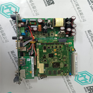


产品标题:IC693PWR322F 用于模拟量电源输入输出模块 GE 通用电气
型号:IC693PWR322F 用于模拟量电源输入输出模块
品牌: GE 通用电气
质保:七天验收期,质保期一年
发货期:1-3个工作日
产品图片展示
产品详情资料
接通电源
输入/输出模块及其附属电缆连接器用螺钉固定。这个
在24 VDC工作电压之前,必须检查其极性、电平和纹波是否正确
有联系的。
在极性相反的情况下,保险丝可保护I/O模块免受损坏。
9.6功能测试
9.6.1准备功能测试
对于功能测试,请借助
标签和/或文档打印输出“I/O子架”。输入/输出模块的所有自由连接器必须连接到分配的输入/输出机架
分配的电压分配器的电缆连接器。所有控制元件(控制装置)
必须由工厂管理层释放或无辅助电源驱动。
9.6.2中央设备测试
H41q/H51q系统中央设备的基本测试包括:
我们建议在
并将副本保存在柜门的口袋中。应该
必须交换模块,因此必要的信息将立即可用。
注:在此状态下,系统设置用于测试单个线路或组
线路对地绝缘,但如果两条线路绝缘则不绝缘
彼此对抗。否则有损坏的风险。
测试电压和绝缘电阻的指南是IEC/EN
61131-2或DIN VDE 0160/EN 50178。
中央模块切换公交车站编号和换乘率的位置,
通过显示器显示的操作系统版本
协处理器模块F 8621A操作系统EPROM
RS 485接口的开关位置
通信模块切换不同操作模式的位置
模块F8627/F8627X和F8628/F8628X,请参见相应的数据表
I/O总线连接参考附件的数据表
装配套件
启动和维护
41
9.6.3输入/输出子架测试
输入/输出子架中的基本测试包括:
有关I/O总线的结构,请参阅B 9302组装套件的数据表和
H41q装配套件。
输入/输出模块本身没有编码。只有模块的正确位置
必须考虑相应的电缆连接器。现有保险丝模块包括
必须检查保险丝的完整性。此外,24 V电源的正确分配
必须检查需要通过后部PCB总线馈电的此类模块的插槽。
9.6.4打开HIMA PES
连接工作电压后,HIMA PES进入RUN运行,如果
用户程序已加载,系统中未发现错误。
如果显示STOP(停止),程序可以通过ELOP II(运行状态)启动。如果出现以下情况,则会出现错误
这是不可能的。只有在纠正错误后,例如设置正确的开关位置,
正确的连接线,或者可能在更换模块等之后,RUN操作是
起动。
可以通过两个按钮或
通过OLT窗口开始与编程设备通信后。请参阅
操作系统文档。
9.6.5启动编程设备和PES之间的通信
关于编程设备与PES之间通信的构建和启动:请参阅文档一步ELOP II、用户手册操作系统和用户手册
ELOP II资源类型。
通信故障可以通过监控、记录程序(HIKA)进行检查
并对数据通信进行了分析。
有关工具“HIKA”的更多信息,请参阅HIMA服务。
9.7维护
在安全相关应用中,例如使用继电器输出模块时,必须定期对模块进行检修(继电器模块每3年,所有其他模块每10年
年,脱机验证试验,见IEC/EN 61508-4,3.8.5段)。
我们建议每五年更换一次电源中的电解电容器。
耦合模块F 7553(仅
H51q系统)
编码机架的开关位置
到资源类型
接线,尤其是看门狗信号,
请参阅组装套件的数据表
和安全员Switching on Power Supply
The input/output modules and their appertaining cable connectors are fixed with screws. The
24 VDC operation voltage has to be checked for correct polarity, level and ripple before it is
connected.
In case of reverse polarity a fuse protects the I/O module of damages.
9.6 Functional Testing
9.6.1 Preparing Functional Testing
For functional testing check the equipment of the control cabinet completely with help of the
label and/or documentation printout "I/O subrack". All free connectors of the input/output modules have to be connected to the allocated input/output racks, and the voltage connections of
the cable connectors to the allocated voltage distributors. All control elements (control devices)
must be released by the factory management or be driven without auxiliary power.
9.6.2 Testing in the Central Devices
The essential tests in the central devices of the H41q/H51q system are:
We recommend marking all required switch positions etc. in copies of the data sheets of the
respective control cabinet and keeping the copies in the pocket of the cabinet door. Should
modules have to be exchanged, the necessary information will thus be immediately available.
Note In this state the system is set up for testing if individual lines or a group
of lines are insulated against earth, but not if two lines are insulated
against each other. Otherwise there is a risk of damage.
The guideline for test voltages and insulating resistance is IEC/EN
61131-2 or DIN VDE 0160/EN 50178.
Central modules switch positions for bus station no. and transfer rate,
version of the operation system via display
Coprocessor module F 8621A operating system EPROM
switch positions for RS 485 interface
Communication modules switch positions for different operating modes for
modules F8627/F8627X and F8628/F8628X, see corresponding data sheet
I/O bus connection refer to the data sheet of the appertaining
assembly kit
Startup and Maintenance
41
9.6.3 Testing in the Input/Output Subracks
The essential tests in the input/output subracks are:
For the construction of the I/O bus refer to the data sheets of the B 9302 assembly kit and of
the H41q assembly kits.
The input/output modules themselves have no coding. Only the correct position of the modules
and the corresponding cable connector must be regarded. The existing fuse modules including
fuses have to be checked for completeness. Also the correct assignment of the 24 V supply to
the slots of such modules, which need the feeding via the rear PCB bus, has to be checked.
9.6.4 Switching on the HIMA PES
After the operating voltage has been connected, the HIMA PES goes into RUN operation, if
the user program has been loaded and no error has been found in the system.
If STOP is displayed the program can be started via ELOP II (RUN state). There is an error if
this is not possible. Only after the correction of the error, e.g. setting the correct switch position,
correct connecting lines, or possibly after the exchange of a module etc. the RUN operation is
started.
Error displays can be called on the diagnostic display of the central module via two buttons or
after the start of the communication to the programming device via OLT window. Refer to the
documentation of the operating system.
9.6.5 Starting the Communication between Programming Device and PES
For construction and startup of the communication between progamming device and PES: refer to the documentations first steps ELOP II, user manual operating system and user manual
ELOP II Resource Type.
Communication faults can be checked by means of a program (HIKA) for monitoring, logging
and analyzing of the data communication.
For more informations about the tool “HIKA” refer to the HIMA service.
9.7 Maintenance
At safety-related applications, e.g. using of relay output modules, the modules have to be overhauled at regular intervals (every 3 years for relay modules, for all other modules every 10
years, OFFLINE proof test, see IEC/EN 61508-4, paragraph 3.8.5).
We recommend exchanging electrolytic capacitors in the power supply every five years.
Coupling module F 7553 (only
H51q systems)
switch position for coding the rack according
to the resource type
Wiring, especially the watchdog signal,
refer to data sheets of the assembly kits
and the safety man
主营产品简介
专注于DCS、PLC、机器人控制系统、大型伺服四大系统领域。
主营产品各种模块/卡件,控制器,触摸屏,伺服驱动器。
优势:供应进口原装正品,专业停产配件,
发货快,货期精准,
主营品牌包括 ABB贝利、GE/FUANC、FOXBORO、英维思TRICONEX 、本特利BENTLY、A-B罗克韦尔、艾默生EMERSON 、OVATION、MOTOROLA、XYVOM、霍尼韦尔HONEYWELL 、力士乐REXROTH、KUKA、NI、DEIF、横河、伍德沃德WOODWARD、瑞恩、施耐德SCHNEIDER 、安川、 穆格MOOG、PROSOFT等品牌
Copyright ©2019-2022 瑞昌明盛自动化设备有限公司 版权所有 赣ICP备2021006016号


