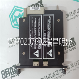
产品标题:POSUM-HW ROFBU 367 306/1 R1C 用于励磁驱动器控制端子 ABB
型号:POSUM-HW ROFBU 367 306/1 R1C 用于励磁驱动器控制端子 ABB
品牌:ABB
质保:七天验收期,质保期一年
发货期:1-3个工作日
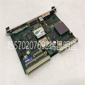
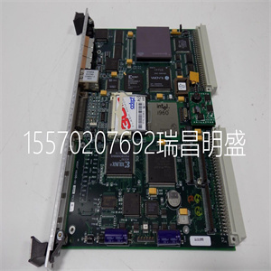
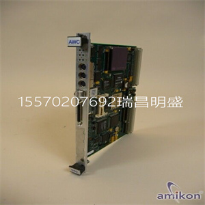
产品图片展示
产品详情资料
本手册中的数字用于说明目的。因为有很多
供应商不能假设与任何特定安装相关的变量
根据数字负责实际使用。
•供应商既不保证操作面板适合您的特定应用,也不对您的产品设计、安装或操作承担责任。安装期间•操作面板设计用于固定安装在平面上,满足以下条件:–无高爆炸风险。–没有强磁场。–无阳光直射没有大的、突然的温度变化。
•根据随附的安装说明安装产品。•根据随附的安装说明将产品接地。•只有合格人员才能安装操作面板。•分离高压电缆、信号电缆和电源电缆。
•在将产品连接到电源插座之前,请确保电源的电压和极性正确。•外围设备必须适合应用和位置。
使用过程中保持操作面板清洁。
•紧急停止和其他安全功能可能无法通过
操作员面板。•不要使用过多,只有合格的人员才能进行维修。•约定的保修适用。•在进行任何清洁或维护操作之前,断开设备与电源的连接。•用软布和温和的清洁剂清洁显示屏和周围的前盖。不正确地更换电池可能会导致爆炸。只能使用供应商推荐的电池。拆卸和报废•操作员面板或其部件应根据当地要求回收
.•以下成分含有可能对人体有害的物质
健康与环境:锂电池、电解电容器和显示器。
3BSE043449R501 13号
第三节安装
空间要求
•安装板厚度:1.5-9.0 mm(0.06-0.35英寸)
•安装操作面板时的空间要求:
外壳上的开口用于空气对流。不要覆盖这些
开口
安装过程第3节安装
14 3BSE043449R501号
安装过程
1.打开包装并检查交货情况。如果发现损坏,请通知供应商。
2.将面板切口放在操作员面板所在的位置,沿着
孔的外侧,并根据标记进行切割。如果访问
需要文本条,请在左下角添加额外空间。
安装期间,将操作面板放在稳定的表面上。
掉落或让其掉落可能会造成损坏。
x 6个
面板切口245.5 x 138.5 mm
(9.67 x 5.45英寸)
5.0毫米
18.0毫米
用于文本条
(0.20英寸)
(0.71英寸)
第三节安装安装工艺
3BSE043449R501 15号
3.使用所有紧固孔和
提供的支架和螺钉:
4.按指定顺序连接电缆。
确保操作员面板和控制器系统
相同的电气接地(参考电压水平),
否则可能会出现通信错误。
使用M5螺钉和接地导线(短至
可能),横截面至少为2.5 mm2。
-仅使用屏蔽通信电缆。
-将高压电缆与信号电缆和电源电缆分开。
-操作员面板必须达到环境温度
在启动之前。如果形成冷凝,确保
操作面板在连接到电源插座之前是干燥的。
-确保电源的电压和极性为
对的The figures in this manual serves an illustrative purpose. Because of the many
variables associated with any particular installation, the supplier cannot assume
responsibility for actual use based on the figures.
• The supplier neither guarantees that the operator panel is suitable for yourparticular application, nor assumes responsibility for your product design,installation or operation.During Installation• The operator panel is designed for stationary installation on a plane surface,where the following conditions are fulfilled:– no high explosive risks.– no strong magnetic fields.– no direct sunlight.– no large, sudden temperature changes.
• Install the product according to the accompanying installation instructions.• Ground the product according to the accompanying installation instructions.• Only qualified personnel may install the operator panel.• Separate the high voltage, signal and supply cables.
• Make sure that the voltage and polarity of the power source is correct beforeconnecting the product to the power outlet.• Peripheral equipment must be appropriate for the application and location.
During Use Keep the operator panel clean.
• Emergency stop and other safety functions may not be controlled from the
operator panel.• Do not use too muOnly qualified personnel should carry out repairs.• The agreed warranty applies.• Before carrying out any cleaning or maintenance operations, disconnect theequipment from the electrical supply.• Clean the display and surrounding front cover with a soft cloth and milddetergent. Replacing the battery incorrectly may result in explosion. Only use batteriesrecommended by the supplier.Dismantling and Scrapping• The operator panel or parts thereof shall be recycled according to local
.• The following components contain substances that might be hazardous to
health and the environment: lithium battery, electrolytic capacitor and display.
3BSE043449R501 13
Section 3 Installation
Space Requirements
• Installation plate thickness: 1.5 - 9.0 mm (0.06 - 0.35 inch)
• Space requirements when installing the operator panel:
The openings on the enclosure are for air convection. Do not cover these
openings
Installation Process Section 3 Installation
14 3BSE043449R501
Installation Process
1. Unpack and check the delivery. If damage is found, notify the supplier.
2. Place the panel cut out where the operator panel is to be situated, draw along
the outer sides of the holes and cut according to the markings. If access to the
text strip is needed, add extra space in the lower left corner.
Place the operator panel on a stable surface during installation.
Dropping it or letting it fall may cause damage.
x 6
Panel cut out 245.5 x 138.5 mm
(9.67 x 5.45 inch)
5.0 mm
18.0 mm
For text strip
(0.20 inch)
(0.71 inch)
Section 3 Installation Installation Process
3BSE043449R501 15
3. Secure the operator panel in position, using all the fastening holes and the
provided brackets and screws:
4. Connect the cables in the specified order.
Ensure that the operator panel and the controller system have
the same electrical grounding (reference voltage level),
otherwise errors in communication may occur.
Use an M5 screw and a grounding conductor (as short as
possible) with a cross-section of minimum 2.5 mm2.
- Use only shielded communication cables.
- Separate high voltage cables from signal and supply cables.
- The operator panel must be brought to ambient temperature
before it is started up. If condensation forms, ensure that the
operator panel is dry before connecting it to the power outlet.
- Ensure that the voltage and polarity of the power source is
correct
主营产品简介
专注于DCS、PLC、机器人控制系统、大型伺服四大系统领域。
主营产品各种模块/卡件,控制器,触摸屏,伺服驱动器。
优势:供应进口原装正品,专业停产配件,
发货快,货期精准,
主营品牌包括 ABB贝利、GE/FUANC、FOXBORO、英维思TRICONEX 、本特利BENTLY、A-B罗克韦尔、艾默生EMERSON 、OVATION、MOTOROLA、XYVOM、霍尼韦尔HONEYWELL 、力士乐REXROTH、KUKA、NI、DEIF、横河、伍德沃德WOODWARD、瑞恩、施耐德SCHNEIDER 、安川、 穆格MOOG、PROSOFT等品牌