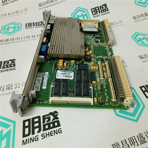
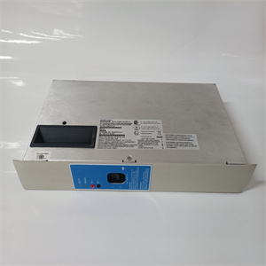
BRC100

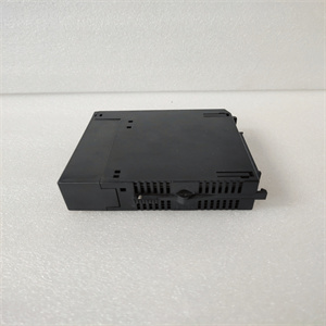
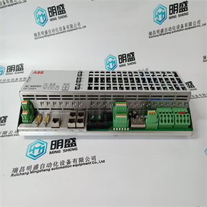
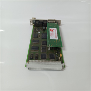
ABB XV C770 AE 3BHB006414R0001
带的位置必须与
这些插槽允许插入模块。您可以在
用于接收此模块的I/O机箱,左侧的连接器除外
为适配器或处理器模块保留。将键带放置在
背板连接器上标记了以下编号:
10至12岁
20至22岁
如果重新设计系统并重新布线,您可以更改这些键的位置
需要插入不同的模块。
安装输出模块
要在1771 I/O机箱中安装交流输出模块,请执行以下步骤
如下所示。
注意:断开1771 I/O机箱的电源
拆卸或安装前的底板和现场接线臂
I/O模块。
无法断开底板或现场接线的电源
arm可能导致模块损坏、性能下降,
或受伤。
未能从背板上断开电源可能会导致
由于可能的意外事故而导致的伤害或设备损坏
活动
1.关闭I/O机箱的电源。
2.将印刷电路板放在塑料轨道的后部模块上
插槽的顶部和底部,用于将模块引导到位。
3.请勿将模块强行插入背板连接器。应用牢固,均匀
对模块施加压力,使其正确就位。
4.将机箱闩锁扣在模块顶部,以固定其位置。
5.将现场接线臂连接至模块。
6.如图1所示,将接线连接至现场接线臂
ABB XV C770 AE 3BHB006414R0001

ABB XV C770 AE 3BHB006414R0001
rd is slotted in two places on the rear edge. The
position of the keying bands on the backplane connector must correspond to
these slots to allow insertion of the module. You can key any connector in an
I/O chassis to receive this module except for the left-most connector
reserved for adapter or processor modules. Place keying bands between the
following numbers labeled on the backplane connector:
Between 10 and 12
Between 20 and 22
You can change the position of these keys if system redesign and rewiring
makes insertion of a different module necessary.
Installing the Output Module
To install the ac output module in your 1771 I/O chassis, follow the steps
listed below.
ATTENTION: Remove power from the 1771 I/O chassis
backplane and field wiring arm before removing or installing an
I/O module.
Failure to remove power from the backplane or field wiring
arm could cause module damage, degradation of performance,
or injury.
Failure to remove power from the backplane could cause
injury or equipment damage due to possible unexpected
operation.
1. Turn off power to the I/O chassis.
2. Place the printed circuit board on the rear module in the plastic tracks
at the top and bottom of the slot that guide the module into position.
3. Do not force the module into its backplane connector. Apply firm, even
pressure on the module to seat it properly.
4. Snap the chassis latch over the top of the module to secure its position.
5. Connect the fielad wiring arm to the module.
6. Make wiring connections to the field wiring arm as indicated in Figure 1
ABB XV C770 AE 3BHB006414R0001