

主营产品简介
专注于DCS、PLC、机器人控制系统、大型伺服四大系统领域。
主营产品各种模块/卡件,控制器,触摸屏,伺服驱动器。
优势:供应进口原装正品,专业停产配件,
发货快,货期精准,
主营品牌包括 ABB贝利、GE/FUANC、FOXBORO、英维思TRICONEX 、本特利BENTLY、A-B罗克韦尔、艾默生EMERSON 、OVATION、MOTOROLA、XYVOM、霍尼韦尔HONEYWELL 、力士乐REXROTH、KUKA、NI、DEIF、横河、伍德沃德WOODWARD、瑞恩、施耐德SCHNEIDER 、安川、 穆格MOOG、PROSOFT等品牌
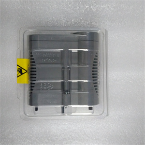
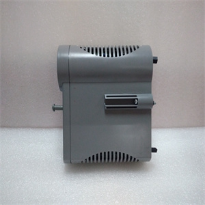
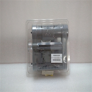
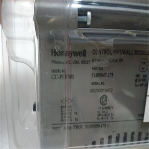
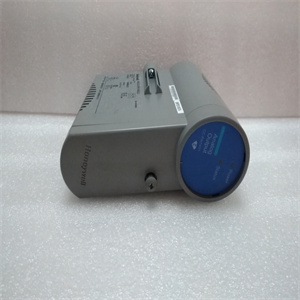
产品图片展示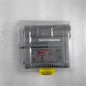
产品详情资料
装绝缘放大器。图3-28绝缘放大器的典型连接表3-7。输入和输出范围默认设置范围S1 S2输入输出1 2 3 1 2 3×0至±10 V 0至±10V×0至5V 4至20 mA×0至10V 4至20mA×0至5 V 0至20 mA x×0±10V 0±20 mA×接地信号0 V+24 V 0 V+-+-+5 6 3 4 7 8信号0 V+24 V 0 V+-+----5 6 3 7 8 PXUB 201–1 2 3 ON S1 1 2 3 ON S2 1 2 2 3 ON S2 1 1 2 3 ONS2输出:4至20mA输入:0至10 V输出:0至±10 V输入:0到±10 V张力电子设备PFEA113,用户手册3章调试3-50 3BSE029382R0101版本C多四个PXUB 201或PXKB 201(A、B、C和D),见下图,可安装在PFEA113(IP65版本)内。根据订单信息,PXUB 201输出预设为出厂电压或电流。表3-8.设置带宽默认带宽S2,位置3(×=ON)×10 kHz 10 Hz×四个PXUB 201或PXKB 201张力电子元件PFEA113,用户手册4.1节关于本章3BSE029382R0101版本C 4-14章操作4.1关于本章您的测量系统在正常操作期间不需要任何注意。只要系统打开,测量就会持续运行。但是,您需要知道如何启动和关闭系统,请参阅4.4节“启动和关闭”。4.2安全说明在开始任何操作工作之前,请阅读并遵循1章“简介”中给出的安全说明。然而,如果地方法规更严格,则应优先考虑。4.3操作装置LED指示灯和操作键如图4-1所示。图4-1。操作装置电源状态背光LCD显示屏后退后退后退后退前进正常(确认)LED“电源”LED“状态”或取消张力电子PFEA113,用户手册4章操作4-2 3BSE029382R0101 C版4.4启动和关闭4.4.1启动使用外部ON/OFF开关(非ABB提供)启动和关闭张力电子设备。正常操作期间,无需操作员采取任何行动。1.检查主张力控制机械是否准备好正常运行。2.通过将外部on/OFF开关设置为on位置来打开张力电子设备。对于IP 65版本(NEMA 4),也将内部开关设置为“on”。3.检查:-显示屏点亮-“电源”指示灯点亮-“状态”指示灯亮起(绿灯)。红灯指示错误。4.4.2关闭通过将外部ON/OFF开关设置为OFF位置来关闭张力电子设备。4.5正常运行测量设备应打开,以获得佳测量结果。这使得称重传感器和电子设备能够在稳定的温度条件下工作。测量设备设计用于连续操作。The insulation amplifier is connected to the tension electronics voltage output. S1 is normally set for voltage 1:1 ratio. The output is selected to generate a voltage or current output by means of switch S1 and S2. Slower response is selected by means of switch S2, position 3. The switches are located inside the unit. Figure 3-27. Insulation Amplifier PXUB 201 You must open the insulation amplifier to be able to set the switches S1 and S2. 1. Demount the insulation amplifier from the DIN rail. Use a screw driver to unload the spring at the bottom of the insulation amplifier. 2. Press down the snap-locks on both sides of the insulation amplifier. 3. Pull the top lid open, until you see both the switches S1 and S2. S2 1 2 3 ON S1 1 2 3 ON Top lid Snap-lock Snap-lock Pull out the top lid, after releasing the snap-locks. To release Spring lock Tension Electronics PFEA113, User Manual Section 3.14.1 Insulation Amplifier PXUB 201 3BSE029382R0101 Rev C 3-49 4. Set the switches S1 and S2. 5. Slide back the top lid to locked position. 6. Remount the insulation amplifier on the DIN rail. Figure 3-28. Typical Connection of the Insulation Amplifier Table 3-7. Setting of Input and Output Range Default Range S1 S2 Input Output 1 2 3 1 2 3 × 0 to ±10 V 0 to ±10 V × × 0 to 5 V 4 to 20 mA × 0 to 10 V 4 to 20 mA × 0 to 5 V 0 to 20 mA × × 0 ± 10 V 0 ± 20 mA × Earth Earth Signal 0 V +24 V 0 V + - + - + 5 6 3 4 7 8 Signal 0 V +24 V 0 V + - + - + – 5 6 3 4 7 8 PXUB 201 PXUB 201 – 1 2 3 ON S1 1 2 3 ON S2 1 2 3 ON S1 1 2 3 ON S2 Output: 4 to 20 mA Input: 0 to 10 V Output: 0 to ± 10 V Input: 0 to ± 10 V Tension Electronics PFEA113, User Manual Chapter 3 Commissioning 3-50 3BSE029382R0101 Rev C Up to Four PXUB 201 or PXKB 201 (A, B, C and D), see the figure below, can be mounted inside the PFEA113 (IP65-version). The PXUB 201 outputs are pre-set to either voltage or current from factory according to order information. Table 3-8. Setting of Bandwidth Default Bandwidth S2, position 3 (× = ON) × 10 kHz 10 Hz × Four PXUB 201 or PXKB 201 Tension Electronics PFEA113, User Manual Section 4.1 About this Chapter 3BSE029382R0101 Rev C 4-1 Chapter 4 Operation 4.1 About this Chapter Your measurement system does not need any attention during normal operation. Measurement runs continuously as long as the system is switched on. However, you need to know how to start and shut down the system, see Section 4.4 Start-up and shut-down. 4.2 Safety Instructions Read and follow the safety instructions given in Chapter 1 Introduction, before starting any operation work. However, local statutory regulations, if stricter, are to take precedence. 4.3 Operating Devices The LED-indicators and operator keys are described in Figure 4-1. Figure 4-1. Operating Devices Power Status Backlit LCD display Step back Step down Step up OK (acknowledgment) LED “Power” LED “Status” or cancel Tension Electronics PFEA113, User Manual Chapter 4 Operation 4-2 3BSE029382R0101 Rev C 4.4 Start-up and shut-down 4.4.1 Start-up The tension electronics i
Copyright ©2019-2022 瑞昌明盛自动化设备有限公司 版权所有 赣ICP备2021006016号


