


主营产品简介
专注于DCS、PLC、机器人控制系统、大型伺服四大系统领域。
主营产品各种模块/卡件,控制器,触摸屏,伺服驱动器。
优势:供应进口原装正品,专业停产配件,
发货快,货期精准,
主营品牌包括 ABB贝利、GE/FUANC、FOXBORO、英维思TRICONEX 、本特利BENTLY、A-B罗克韦尔、艾默生EMERSON 、OVATION、MOTOROLA、XYVOM、霍尼韦尔HONEYWELL 、力士乐REXROTH、KUKA、NI、DEIF、横河、伍德沃德WOODWARD、瑞恩、施耐德SCHNEIDER 、安川、 穆格MOOG、PROSOFT等品牌
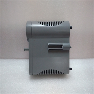
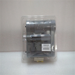
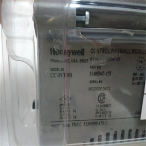
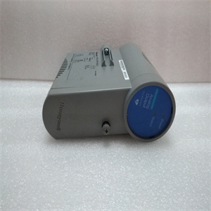
产品图片展示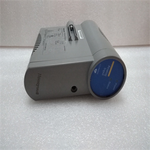
产品详情资料
O 压或电流。表3-8.设置带宽默认带宽S2,位置3(×=ON)×10 kHz 10 Hz×四个PXUB 201或PXKB 201张力电子元件PFEA113,用户手册4.1节关于本章3BSE029382R0101版本C 4-14章操作4.1关于本章您的测量系统在正常操作期间不需要任何注意。只要系统打开,测量就会持续运行。但是,您需要知道如何启动和关闭系统,请参阅4.4节“启动和关闭”。4.2安全说明在开始任何操作工作之前,请阅读并遵循1章“简介”中给出的安全说明。然而,如果地方法规更严格,则应优先考虑。4.3操作装置LED指示灯和操作键如图4-1所示。图4-1。操作装置电源状态背光LCD显示屏后退后退后退后退前进正常(确认)LED“电源”LED“状态”或取消张力电子PFEA113,用户手册4章操作4-2 3BSE029382R0101 C版4.4启动和关闭4.4.1启动使用外部ON/OFF开关(非ABB提供)启动和关闭张力电子设备。正常操作期间,无需操作员采取任何行动。1.检查主张力控制机械是否准备好正常运行。2.通过将外部on/OFF开关设置为on位置来打开张力电子设备。对于IP 65版本(NEMA 4),也将内部开关设置为“on”。3.检查:-显示屏点亮-“电源”指示灯点亮-“状态”指示灯亮起(绿灯)。红灯指示错误。4.4.2关闭通过将外部ON/OFF开关设置为OFF位置来关闭张力电子设备。4.5正常运行测量设备应打开,以获得佳测量结果。这使得称重传感器和电子设备能够在稳定的温度条件下工作。测量设备设计用于连续操作。The insulation amplifier is connected to the tension electronics voltage output. S1 is normally set for voltage 1:1 ratio. The output is selected to generate a voltage or current output by means of switch S1 and S2. Slower response is selected by means of switch S2, position 3. The switches are located inside the unit. Figure 3-27. Insulation Amplifier PXUB 201 You must open the insulation amplifier to be able to set the switches S1 and S2. 1. Demount the insulation amplifier from the DIN rail. Use a screw driver to unload the spring at the bottom of the insulation amplifier. 2. Press down the snap-locks on both sides of the insulation amplifier. 3. Pull the top lid open, until you see both the switches S1 and S2. S2 1 2 3 ON S1 1 2 3 ON Top lid Snap-lock Snap-lock Pull out the top lid, after releasing the snap-locks. To release Spring lock Tension Electronics PFEA113, User Manual Section 3.14.1 Insulation Amplifier PXUB 201 3BSE029382R0101 Rev C 3-49 4. Set the switches S1 and S2. 5. Slide back the top lid to locked position. 6. Remount the insulation amplifier on the DIN rail. Figure 3-28. Typical Connection of the Insulation Amplifier Table 3-7. Setting of Input and Output Range Default Range S1 S2 Input Output 1 2 3 1 2 3 × 0 to ±10 V 0 to ±10 V × × 0 to 5 V 4 to 20 mA × 0 to 10 V 4 to 20 mA × 0 to 5 V 0 to 20 mA × × 0 ± 10 V 0 ± 20 mA × Earth Earth Signal 0 V +24 V 0 V + - + - + 5 6 3 4 7 8 Signal 0 V +24 V 0 V + - + - + – 5 6 3 4 7 8 PXUB 201 PXUB 201 – 1 2 3 ON S1 1 2 3 ON S2 1 2 3 ON S1 1 2 3 ON S2 Output: 4 to 20 mA Input: 0 to 10 V Output: 0 to ± 10 V Input: 0 to ± 10 V Tension Electronics PFEA113, User Manual Chapter 3 Commissioning 3-50 3BSE029382R0101 Rev C Up to Four PXUB 201 or PXKB 201 (A, B, C and D), see the figure below, can be mounted inside the PFEA113 (IP65-version). The PXUB 201 outputs are pre-set to either voltage or current from factory according to order information. Table 3-8. Setting of Bandwidth Default Bandwidth S2, position 3 (× = ON) × 10 kHz 10 Hz × Four PXUB 201 or PXKB 201 Tension Electronics PFEA113, User Manual Sectio
Copyright ©2019-2022 瑞昌明盛自动化设备有限公司 版权所有 赣ICP备2021006016号


